EasyManuals Logo

GE L90 User Manual

GE L90
900 pages
To Next Page IconTo Next Page
To Previous Page IconTo Previous Page
Page #535 background imageLoading...
Page #535 background image
CHAPTER 5: SETTINGS GROUPED ELEMENTS
L90 LINE CURRENT DIFFERENTIAL SYSTEM – INSTRUCTION MANUAL 5-311
5
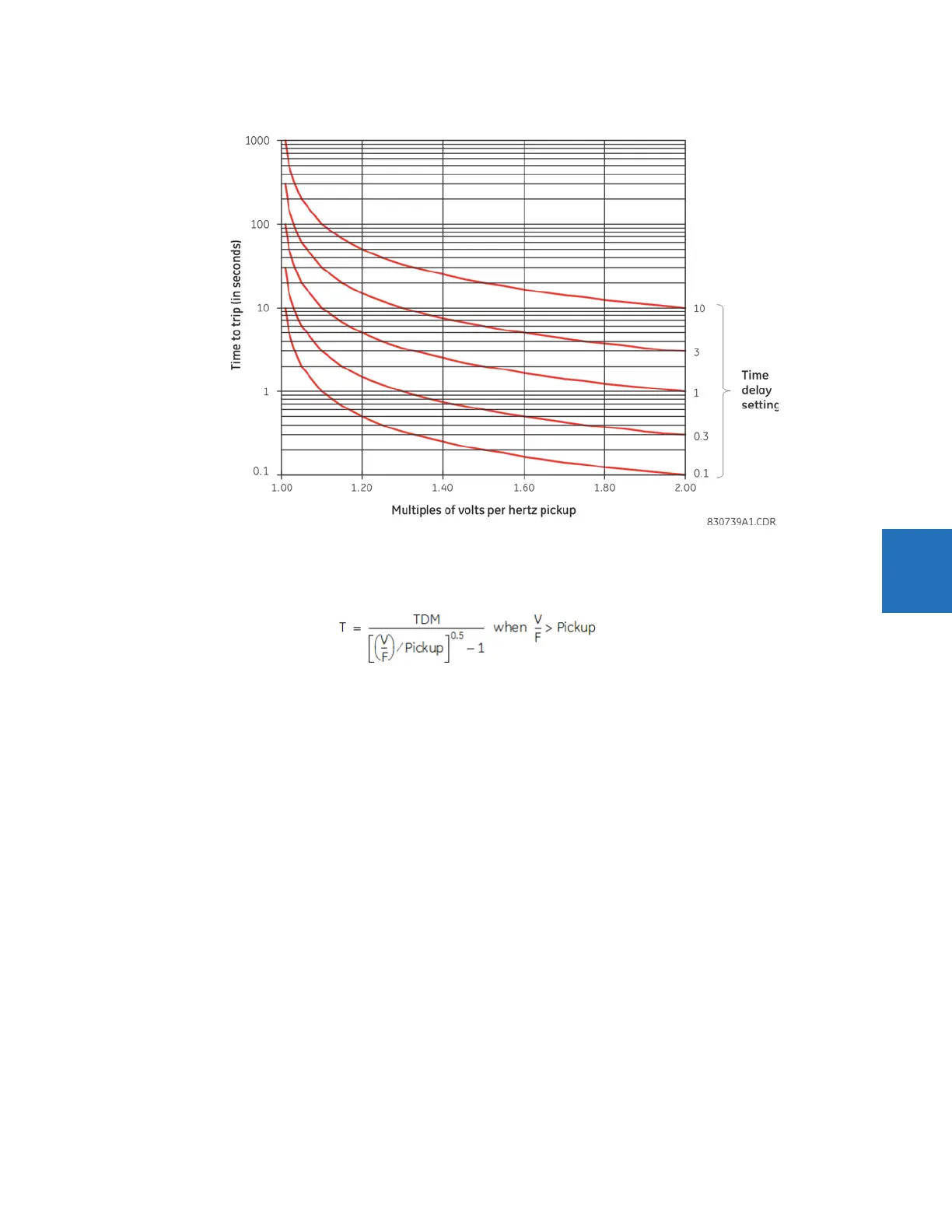
Figure 5-175: Volts-per-hertz curves, inverse curve B
Inverse curve C
The curve for the Volts/Hertz Inverse Curve C shape is derived from the formula:
Eq. 5-39
where
T = Operating Time
TDM = Time Delay Multiplier (delay in sec.)
V = fundamental RMS value of voltage (pu)
F = frequency of voltage signal (pu)
Pickup = volts-per-hertz pickup setpoint (pu)
The figure shows the volts/hertz inverse C curves.

Table of Contents

Questions and Answers:

Question and Answer IconNeed help?

Do you have a question about the GE L90 and is the answer not in the manual?

GE L90 Specifications

General IconGeneral
CommunicationEthernet, Serial
MountingPanel Mount
Frequency50/60 Hz
InputsDigital, Analog
OutputsRelay
ControlLocal, Remote
Communication InterfaceIEC 61850, DNP3, Modbus
Protection FunctionsDifferential, Ground Fault
Standards ComplianceIEC, IEEE

Related product manuals