CHAPTER 5: SETTINGS GROUPED ELEMENTS
L90 LINE CURRENT DIFFERENTIAL SYSTEM – INSTRUCTION MANUAL 5-303
5
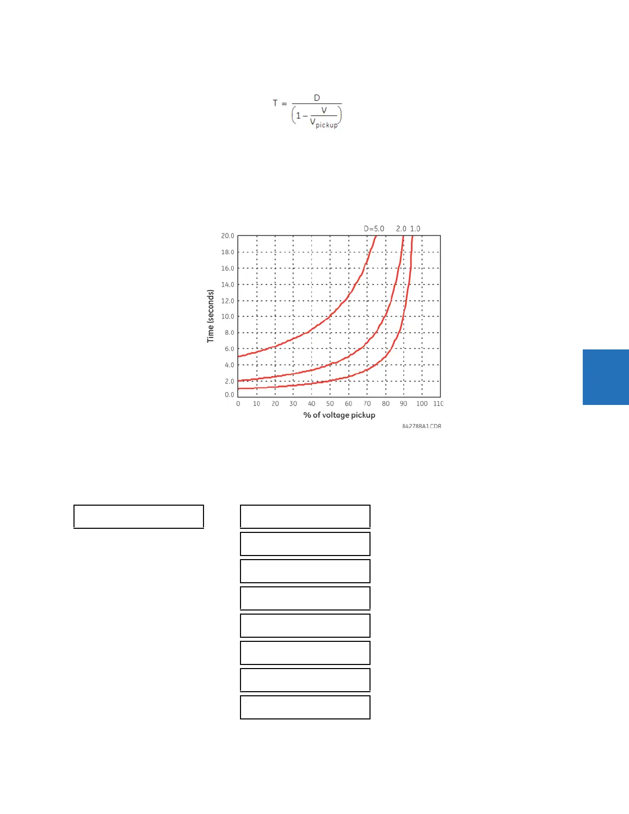
The undervoltage delay setting defines the family of curves shown as follows.
Eq. 5-36
where
T = operating time
D = undervoltage delay setting (D = 0.00 operates instantaneously)
V = secondary voltage applied to the relay
V
pickup
= pickup level
Figure 5-167: Inverse time undervoltage curves
At 0% of pickup, the operating time equals the
PHASE UNDERVOLTAGE DELAY setting.
5.7.14.2 Phase undervoltage (ANSI 27P, IEC PTUV)
SETTINGS GROUPED ELEMENTS SETTING GROUP 1(6) VOLTAGE ELEMENTS PHASE UNDERVOLTAGE1(3)
PHASE
UNDERVOLTAGE1
PHASE UV1
FUNCTION: Disabled
Range: Disabled, Enabled
PHASE UV1 SIGNAL
SOURCE: SRC 1
Range: SRC 1, SRC 2, SRC 3, SRC 4
PHASE UV1 MODE:
Phase to Ground
Range: Phase to Ground, Phase to Phase
PHASE UV1
PICKUP: 1.000 pu
Range: 0.004 to 3.000 pu in steps of 0.001
PHASE UV1
CURVE: Definite Time
Range: Definite Time, Inverse Time
PHASE UV1
DELAY: 1.00 s
Range: 0.00 to 600.00 s in steps of 0.01
PHASE UV1 MINIMUM
VOLTAGE: 0.100 pu
Range: 0.000 to 3.000 pu in steps of 0.001
PHASE UV1 BLOCK:
Off
Range: FlexLogic operand