EasyManuals Logo

GE L90 User Manual

GE L90
900 pages
To Next Page IconTo Next Page
To Previous Page IconTo Previous Page
Page #116 background imageLoading...
Page #116 background image
3-48 L90 LINE CURRENT DIFFERENTIAL SYSTEM – INSTRUCTION MANUAL
PILOT CHANNEL COMMUNICATIONS CHAPTER 3: INSTALLATION
3
Figure 3-53: C37.94SM timing selection switch setting
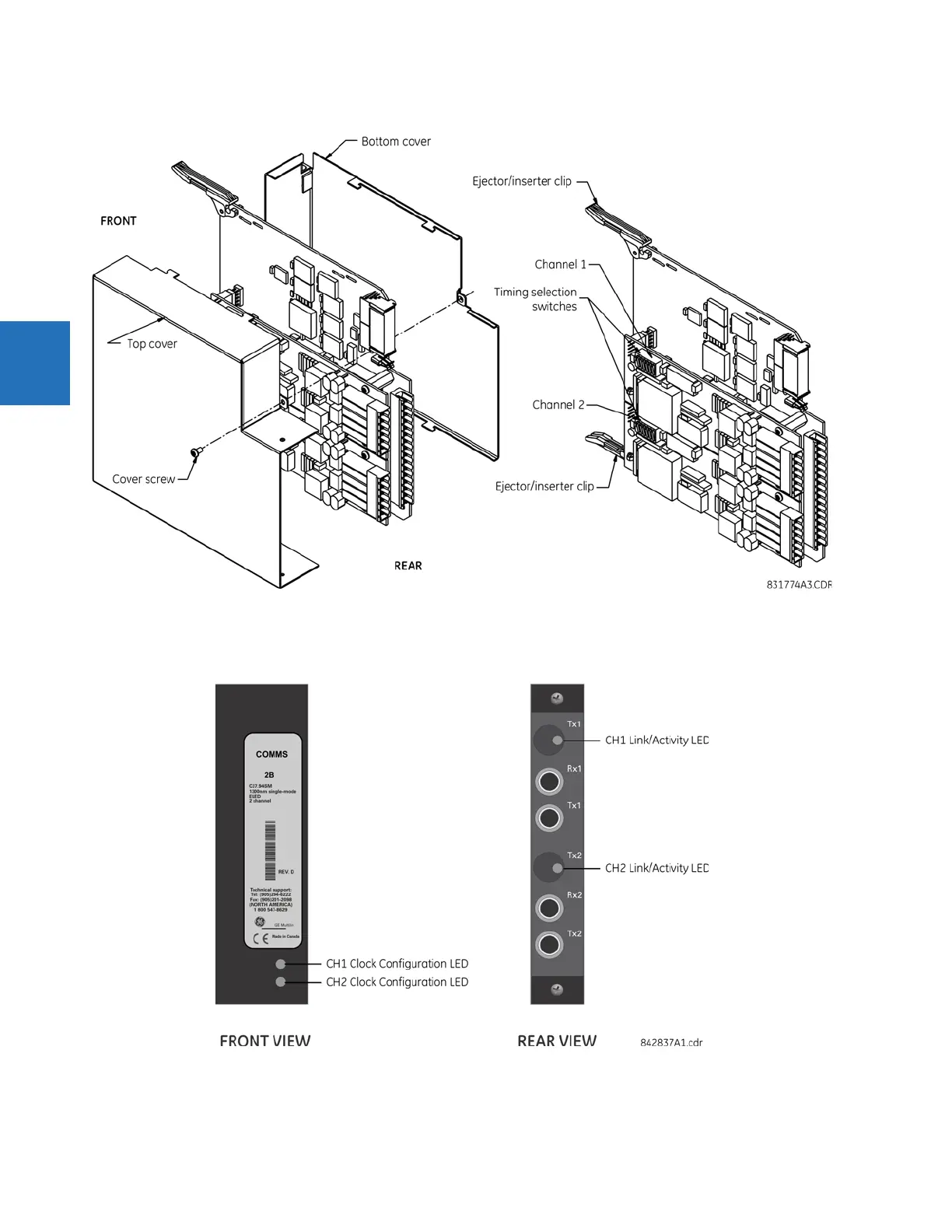
Modules shipped since January 2012 have status LEDs that indicate the status of the DIP switches, as shown in the
following figure.
Figure 3-54: Status LEDs
The clock configuration LED status is as follows:
• Flashing green — loop timing mode while receiving a valid data packet

Table of Contents

Questions and Answers:

Question and Answer IconNeed help?

Do you have a question about the GE L90 and is the answer not in the manual?

GE L90 Specifications

General IconGeneral
CommunicationEthernet, Serial
MountingPanel Mount
Frequency50/60 Hz
InputsDigital, Analog
OutputsRelay
ControlLocal, Remote
Communication InterfaceIEC 61850, DNP3, Modbus
Protection FunctionsDifferential, Ground Fault
Standards ComplianceIEC, IEEE

Related product manuals