4-6 L90 LINE CURRENT DIFFERENTIAL SYSTEM – INSTRUCTION MANUAL
ENERVISTA SOFTWARE INTERFACE CHAPTER 4: INTERFACES
4
Alternatively, the settings template can be applied to online settings, as follows.
1. Select an installed device in the online window of the EnerVista UR Setup window.
2. Right-click the selected device and select the Template Mode > Create Template option.The software prompts for a
template password. This password is required to use the template feature and must be at least four characters in
length.
The software prompts for a template password. This password is required to use the template feature and must be at
least four characters in length.
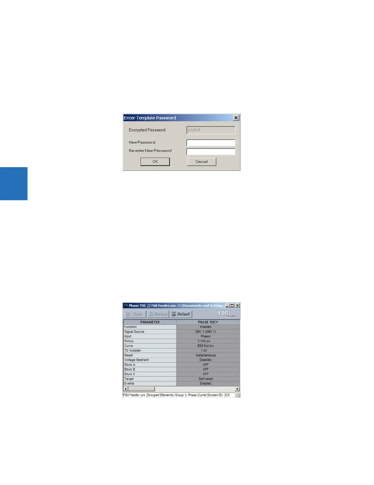
Figure 4-3: Entering a settings file password
3. Enter and re-enter the new password, then click OK to continue.
The online settings template is now enabled. The device is now in template editing mode.
4.1.7.2 Edit the settings template
The settings template editing feature allows the user to specify which settings are available for viewing and modification in
EnerVista UR Setup. By default, all settings except the FlexLogic equation editor settings are locked.
1. Select an installed device or a settings file from the menu on the left side of the EnerVista UR Setup window.
2. Right-click and select the Template Mode > Edit Template option to place the device in template editing mode.
3. If prompted, enter the template password then click OK.
4. Open the relevant settings window that contains settings to be specified as viewable.
By default, all settings are specified as locked and displayed against a grey background. The icon on the upper right of
the settings window also indicates that the EnerVista software is in EDIT mode. The following example shows the
phase time overcurrent settings window in edit mode.
Figure 4-4: Settings template with all settings specified as locked
5. Specify the settings to make viewable by clicking them.
A setting available to view is displayed against a yellow background.