CHAPTER 4: INTERFACES FRONT PANEL INTERFACE
L90 LINE CURRENT DIFFERENTIAL SYSTEM – INSTRUCTION MANUAL 4-15
4
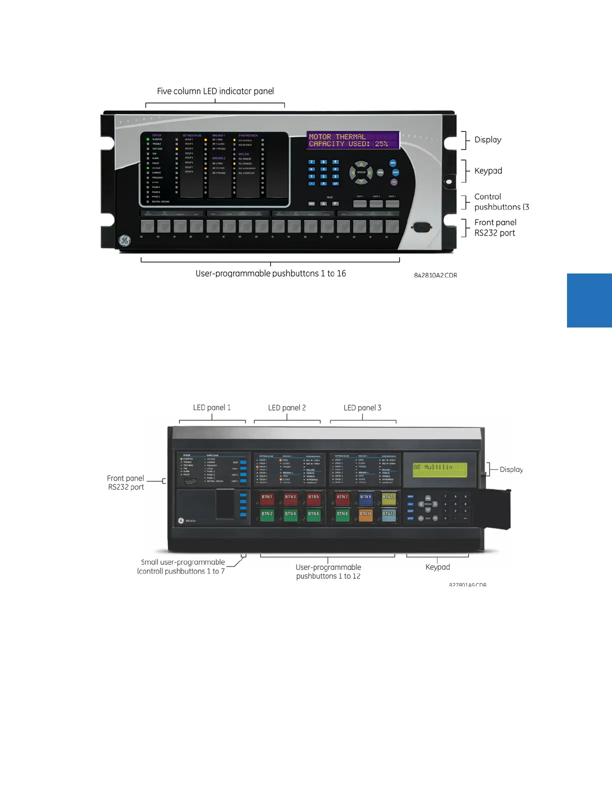
Figure 4-17: Enhanced front panel
4.2.1.2 Standard front panel
The standard front panel consists of LED panels, an RS232 port, keypad, LCD display, control pushbuttons, and optional
user-programmable pushbuttons.
The front panel is hinged to allow easy access to removable modules inside the chassis. There is also a removable dust
cover that is to be removed when accessing the keypad. The standard front panel can be horizontal or vertical. The
following figure shows the horizontal front panel.
Figure 4-18: Standard horizontal front panel
The following figure shows the vertical front panel for relays ordered with the vertical option.