4-18 L90 LINE CURRENT DIFFERENTIAL SYSTEM – INSTRUCTION MANUAL
FRONT PANEL INTERFACE CHAPTER 4: INTERFACES
4
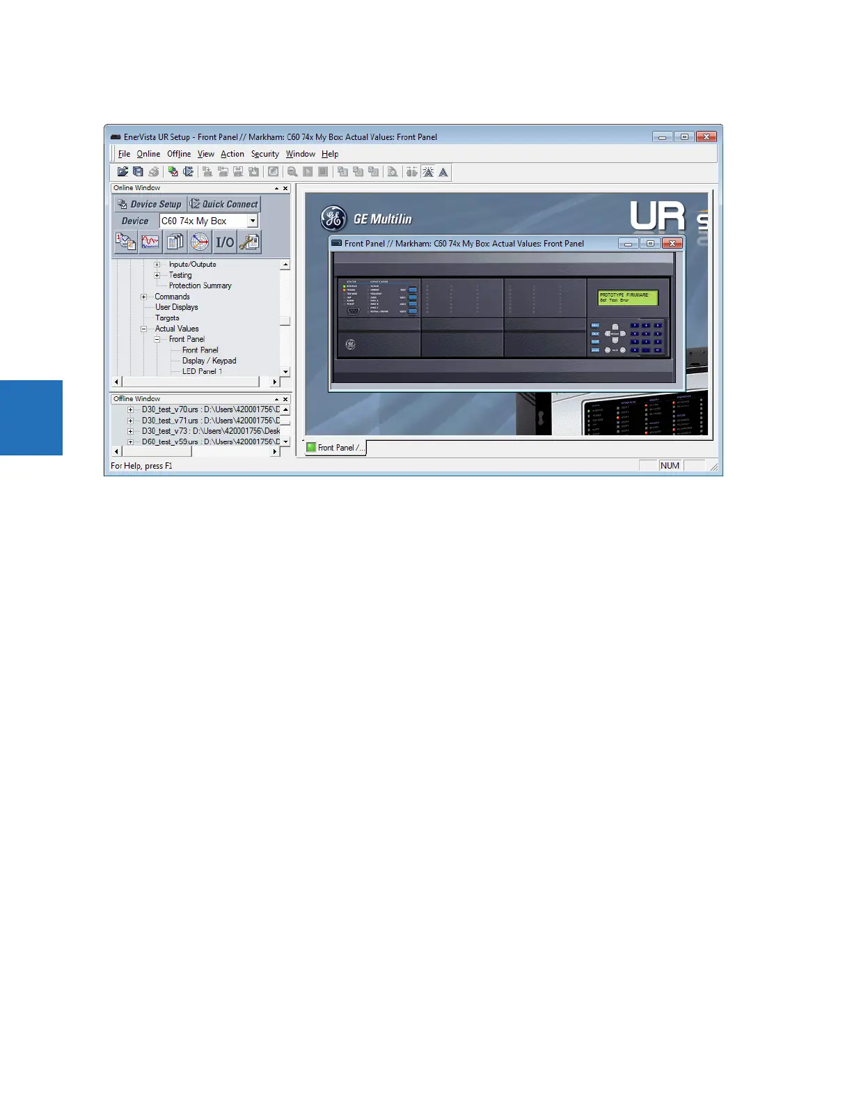
Figure 4-22: Front panel use in the software (C60 shown)
4.2.2.2 Graphical front panel
The graphical front panel has a seven-inch (17.8 cm) color liquid crystal display (LCD). The display provides convenient
access to operational data generated by the relay, enables local control of power system devices, and allows display/
editing of settings.
Header content varies by page. The home page displays any icons for security status, active setting group, active target
messages, and abnormal annunciator alarms present. It shows the date and time of the relay. If the relay synchronizes to
an external time source via PTP, IRIG-B, SNTP, and so on, the date/time is shown in white, and otherwise in yellow. On pages
other than the home page, the header displays the name of the page.
The footer dynamically labels the Tab, or control, pushbuttons immediately below.
Page content displays between the header and footer. The pages are arranged for navigation in a hierarchical structure
similar to that used for the enhanced and standard front panels.