5-144 L90 LINE CURRENT DIFFERENTIAL SYSTEM – INSTRUCTION MANUAL
SYSTEM SETUP CHAPTER 5: SETTINGS
5
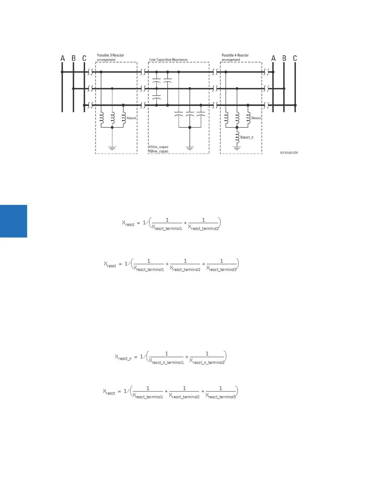
Figure 5-64: Charging current compensation configurations
POSITIVE and ZERO SEQUENCE CAPACITIVE REACTANCE — The values of positive and zero-sequence capacitive reactance of
the protected line are required for charging current compensation calculations. The line capacitive reactance values are
entered in primary kilo-ohms for the total line length.
If shunt reactors are also installed on the line, the resulting value entered in the
POS SEQ CAPACITIVE REACTANCE and ZERO
SEQ CAPACITIVE REACTANCE
settings are calculated as follows:
Three-reactor arrangement — Three identical line reactors (X
react
) solidly connected phase to ground:
Eq. 5-8
Four-reactor arrangement — Three identical line reactors (X
react
) wye-connected with the fourth reactor (X
react_n
)
connected between reactor-bank neutral and the ground.
Eq. 5-9
where
X
1line_capac
= the total line positive-sequence capacitive reactance
X
0line_capac
= the total line zero-sequence capacitive reactance
X
react
= the total reactor inductive reactance per phase. If identical reactors are installed at both line ends, the value of the
inductive reactance is divided by 2 (or 3 for a three-terminal line) before use in the previous equations. If the reactors
installed at both ends of the line are different, the following equations apply:
For two terminal line:
Eq. 5-10
For three terminal line:
Eq. 5-11
where