CHAPTER 5: SETTINGS SYSTEM SETUP
L90 LINE CURRENT DIFFERENTIAL SYSTEM – INSTRUCTION MANUAL 5-169
5
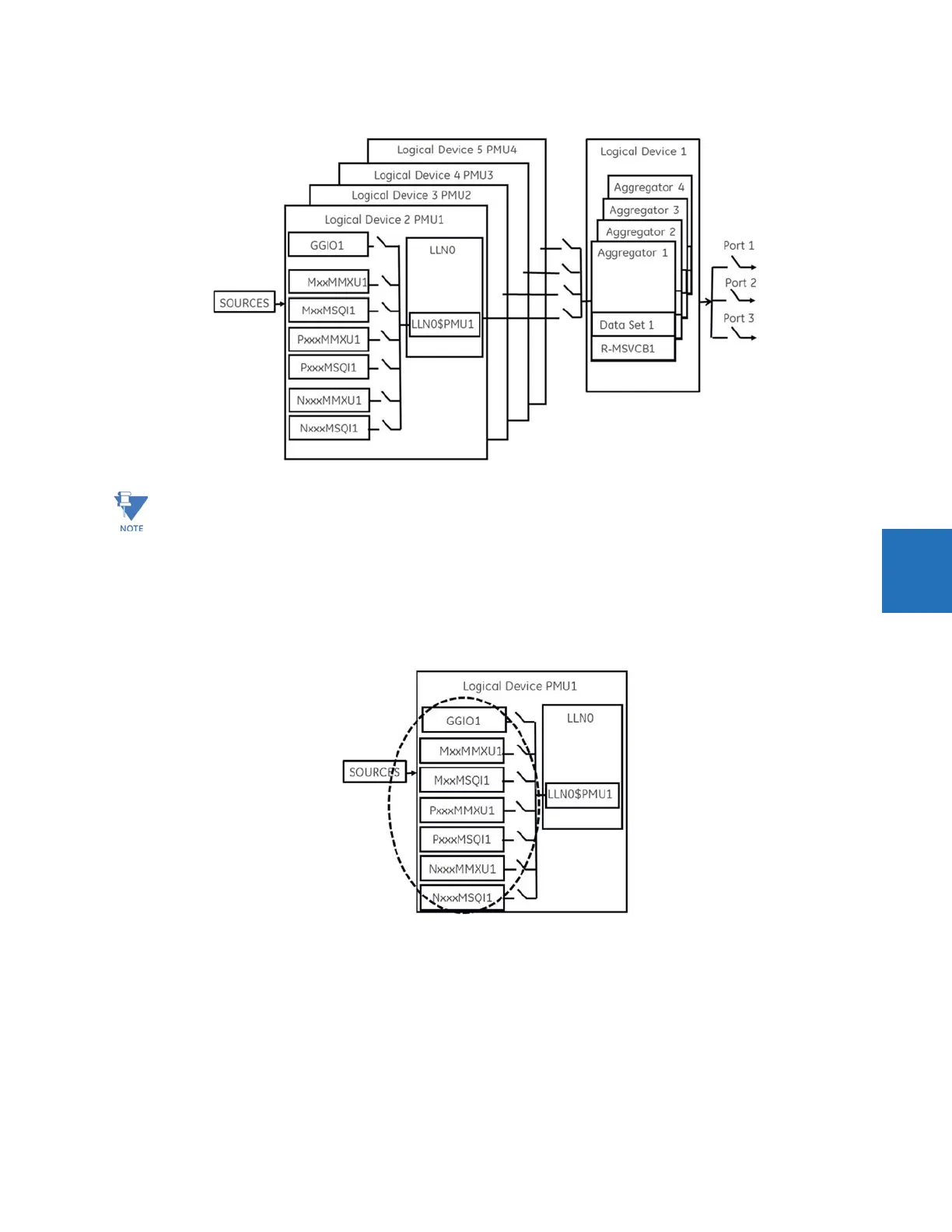
Figure 5-85: N60 example for four logical device PMUs
Depending on the applied filter, the synchrophasors that are produced by PMUs are classified as either P (protection) or M
(Measurement) class synchrophasors. Synchrophasors available within the UR that have no filtering applied are classified
as NONE, which within the standard is classified as PRES OR UNKNOWN under the Calculation Method - ClcMth. Each
Logical Device PMU supports one MxxMMXU, MxxMSQI, PxxxMMXU , PxxxMSQI, NxxMMXU, and one NxxMSQI logical node.
Figure 5-86: Logical nodes supported in each logical device
The following is a summary of LNs that are in each Logical Device (LD2 through LD7):
• PxxxMMXU1 ClcMth = P-Class (Note Vaux is mapped to Vneut of MMXU)
• PxxxMSQI1 ClcMth = P-CLASS
• MxxMMXU1 ClcMth = M-Class (Note Vaux is mapped to Vneut of MMXU)
• MxxMSQI1 ClcMth = M-CLASS
• NxxMMXU1 ClcMth = M-Class (Note Vaux is mapped to Vneut of MMXU)
• NxxMSQI1 ClcMth = M-CLASS
Precise time input to the relay from the international time standard, via either IRIG-B or PTP, is vital for correct
synchrophasor measurement and reporting. For IRIG-B, a DC level shift IRIG-B receiver must be used for the PMU to
output proper synchrophasor values.