5-172 L90 LINE CURRENT DIFFERENTIAL SYSTEM – INSTRUCTION MANUAL
SYSTEM SETUP CHAPTER 5: SETTINGS
5
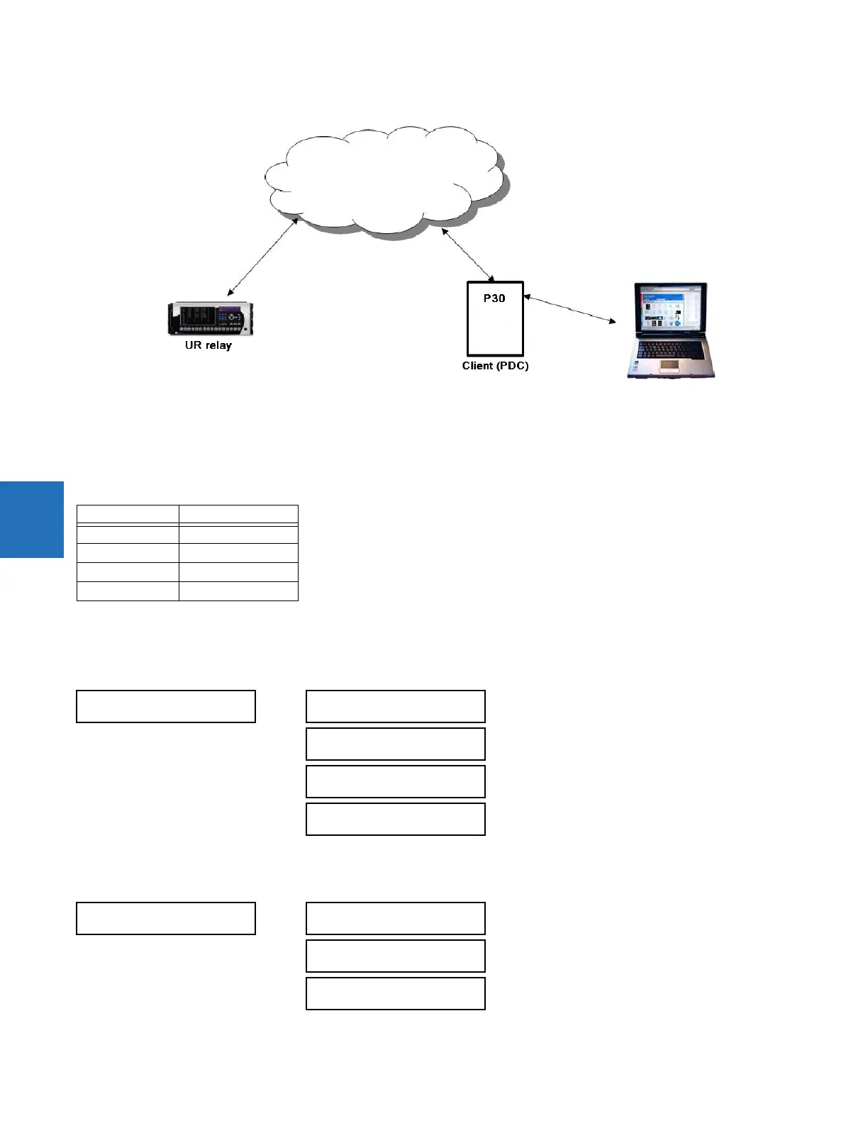
Figure 5-89: CFG-2 based configuration solution
5.5.8.7 Modification of SYNC word in CFG-2 for TR 90-5 data sets
In the CFG-2 file, all relevant information about the data being streamed is included. However, this file does not include the
fact that it describes a 90-5 dataset or the number of Application Service Data Units (datasets). In order to communicate
this information via the CFG-2 file for a given aggregator, when the aggregator is set to 90-5, the version number of the
CFG-2 file (found in bits 0-3 of the frame SYNC word, which is set presently to 2) is set as follows:
5.5.8.8 Settings
The PMU settings are organized as follows.
SETTINGS SYSTEM SETUP PHASOR MEASUREMENT UNIT PHASOR MEASUREMENT UNIT 1
5.5.8.9 Basic configuration
SETTINGS SYSTEM SETUP PHASOR MEASUREMENT UNIT BASIC CONFIGURATION PMU 1
Value (decimal) Number of ASDUs
11 1
12 2
13 3
14 4
PHASOR MEASUREMENT
UNIT 1
PMU 1 BASIC
CONFIGURATION
See below
PMU 1
CALIBRATION
See page 5-176
PMU 1
TRIGGERING
See page 5-177
PMU 1
RECORDING
See page 5-183
PMU 1 BASIC
CONFIGURATION
PMU 1
FUNCTION: Disabled
Range: Enabled, Disabled
PMU 1 IDCODE:
1
Range: 1 to 65534 in steps of 1
PMU 1 STN:
GE-UR-PMU
Range: 32-character ASCII string truncated to 16
characters if mapped into C37.118 Default: GE-UR-PMU