CHAPTER 5: SETTINGS FLEXLOGIC
L90 LINE CURRENT DIFFERENTIAL SYSTEM – INSTRUCTION MANUAL 5-215
5
The non-volatile latches provide a permanent logical flag that is stored safely and do not reset upon restart after the relay
is powered down. Typical applications include sustaining operator commands or permanently blocking relay functions,
such as Autorecloser, until a deliberate interface action resets the latch.
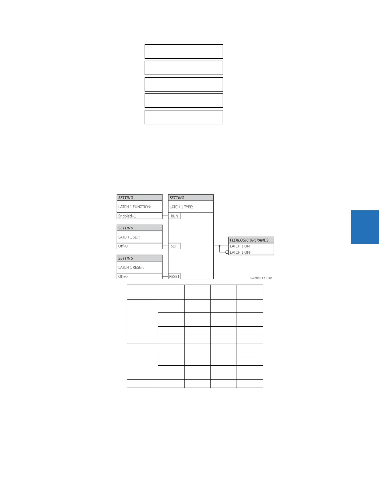
LATCH 1 TYPE — This setting characterizes Latch 1 to be Set- or Reset-dominant.
LATCH 1 SET — If asserted, the specified FlexLogic operands 'sets' Latch 1.
LATCH 1 RESET — If asserted, the specified FlexLogic operand 'resets' Latch 1.
Figure 5-108: Non-volatile latch operation table (N = 1 to 16) and logic
LATCH 1 TYPE:
Reset Dominant
Range: Reset Dominant, Set Dominant
LATCH 1 SET:
Off
Range: FlexLogic operand
LATCH 1 RESET:
Off
Range: FlexLogic operand
LATCH 1
TARGET: Self-reset
Range: Self-reset, Latched, Disabled
LATCH 1
EVENTS: Disabled
Range: Disabled, Enabled
Latch n type Latch n
set
Latch n
reset
Latch n
on
Latch n
off
Reset
Dominant
ON OFF ON OFF
OFF OFF Previous
State
Previous
State
ON ON OFF ON
OFF ON OFF ON
Set
Dominant
ON OFF ON OFF
ON ON ON OFF
OFF OFF Previous
State
Previous
State
OFF ON OFF ON