EasyManuals Logo

GE L90 User Manual

GE L90
900 pages
To Next Page IconTo Next Page
To Previous Page IconTo Previous Page
Page #465 background imageLoading...
Page #465 background image
CHAPTER 5: SETTINGS GROUPED ELEMENTS
L90 LINE CURRENT DIFFERENTIAL SYSTEM – INSTRUCTION MANUAL 5-241
5
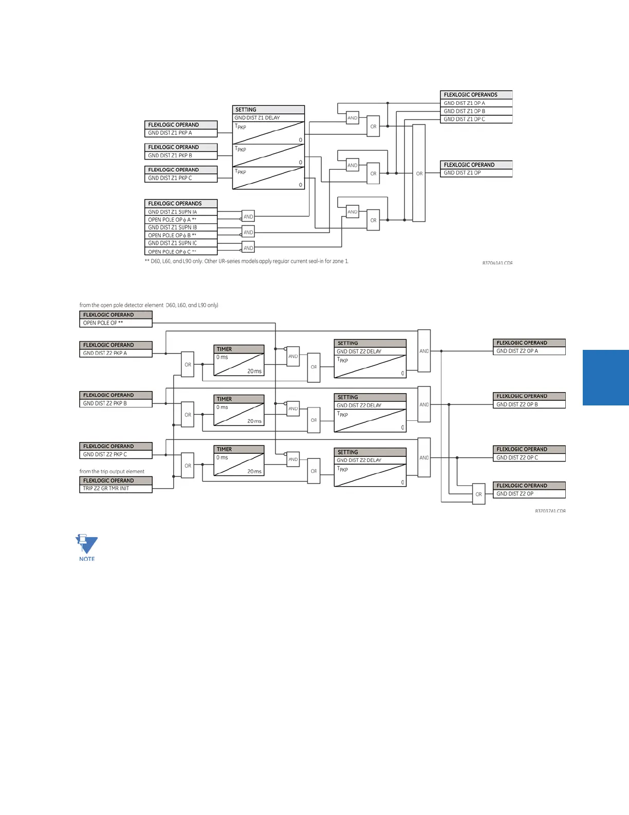
Figure 5-126: Ground distance zone 1 OP scheme
Figure 5-127: Ground distance zone 2 OP scheme
For ground distance zone 2, there is a provision to start the zone timer with the other distance zones or loop pickup
flags to avoid prolonging ground distance zone 2 operation if the fault evolves from one type to another or
migrates from zone 3 or 4 to zone 2. Assign the required zones in the trip output element to accomplish this
functionality.

Table of Contents

Questions and Answers:

Question and Answer IconNeed help?

Do you have a question about the GE L90 and is the answer not in the manual?

GE L90 Specifications

General IconGeneral
CommunicationEthernet, Serial
MountingPanel Mount
Frequency50/60 Hz
InputsDigital, Analog
OutputsRelay
ControlLocal, Remote
Communication InterfaceIEC 61850, DNP3, Modbus
Protection FunctionsDifferential, Ground Fault
Standards ComplianceIEC, IEEE

Related product manuals