CHAPTER 5: SETTINGS GROUPED ELEMENTS
L90 LINE CURRENT DIFFERENTIAL SYSTEM – INSTRUCTION MANUAL 5-289
5
There are two negative-sequence directional overcurrent protection elements available. The element provides both
forward and reverse fault direction indications through its output operands NEG SEQ DIR OC1 FWD and NEG SEQ DIR OC1 REV,
respectively. The output operand is asserted if the magnitude of the operating current is above a pickup level (overcurrent
unit) and the fault direction is seen as forward or reverse, respectively (directional unit).
The overcurrent unit of the element essentially responds to the magnitude of a fundamental frequency phasor of either the
negative-sequence or neutral current as per user selection.
A positive-sequence restraint is applied for better performance: a small user-programmable portion of the positive-
sequence current magnitude is subtracted from the negative or zero-sequence current magnitude, respectively, when
forming the element operating quantity.
I
op
= |I_2| - K x |I_1| or I
op
= 3 x (|I_0| - K x |I_1|) Eq. 5-35
The positive-sequence restraint allows for more sensitive settings by counterbalancing spurious negative-sequence and
zero-sequence currents resulting from
• System unbalances under heavy load conditions
• Transformation errors of current transformers (CTs)
• Fault inception and switch-off transients
The positive-sequence restraint must be considered when testing for pickup accuracy and response time (multiple of
pickup). The positive-sequence restraint is removed for low currents. If the positive-sequence current is less than 0.8 pu,
then the restraint is removed by changing the constant K to zero. This results in better response to high-resistance faults
when the unbalance is very small and there is no danger of excessive CT errors, since the current is low.
The operating quantity depends on the way the test currents are injected into the L90. For single phase injection
•I
op
= ⅓ × (1 – K) × I
injected
for I_2 mode
•I
op
= (1 – K) × I
injected
for I_0 mode if I_1 > 0.8 pu
The directional unit uses the negative-sequence current (I_2) and negative-sequence voltage (V_2).
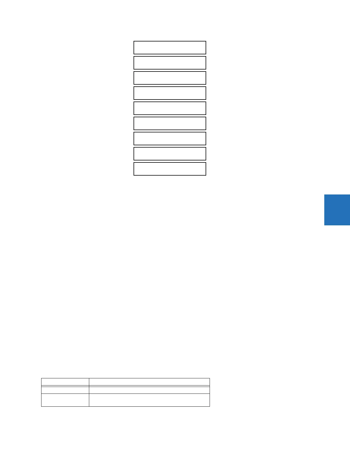
The following tables define the negative-sequence directional overcurrent element.
Table 5-39: Negative-sequence directional overcurrent unit
NEG SEQ DIR OC1 POS-
SEQ RESTRAINT: 0.063
Range: 0.000 to 0.500 in steps of 0.001
NEG SEQ DIR OC1 FWD
ECA: 75° Lag
Range: 0 to 90° Lag in steps of 1
NEG SEQ DIR OC1 FWD
LIMIT ANGLE: 90°
Range: 40 to 90° in steps of 1
NEG SEQ DIR OC1 FWD
PICKUP: 0.050 pu
Range: 0.015 to 30.000 pu in steps of 0.005
NEG SEQ DIR OC1 REV
LIMIT ANGLE: 90°
Range: 40 to 90° in steps of 1
NEG SEQ DIR OC1 REV
PICKUP: 0.050 pu
Range: 0.015 to 30.000 pu in steps of 0.005
NEG SEQ DIR OC1 BLK:
Off
Range: FlexLogic operand
NEG SEQ DIR OC1
TARGET: Self-reset
Range: Self-reset, Latched, Disabled
NEG SEQ DIR OC1
EVENTS: Disabled
Range: Disabled, Enabled
Mode Operating current
Negative-sequence I
op
= |I_2| – K × I_1|
Zero-sequence I
op
= 3 × (|I_0| – K × |I_1|) if |I_1| > 0.8 pu
I
op
= 3 × |I_0| if |I_1| ≤ 0.8 pu