CHAPTER 5: SETTINGS CONTROL ELEMENTS
L90 LINE CURRENT DIFFERENTIAL SYSTEM – INSTRUCTION MANUAL 5-345
5
The voltages V1 and V2 are matched automatically so that the corresponding voltages from the two sources are used
to measure conditions. A phase to phase voltage is used if available in both sources; if one or both of the Sources have
only an auxiliary voltage, this voltage is used. For example, if an auxiliary voltage is programmed to VAG, the
synchrocheck element automatically selects VAG from the other source. If the comparison is required on a specific
voltage, the user can externally connect that specific voltage to auxiliary voltage terminals and then use this "Auxiliary
Voltage" to check the synchronism conditions.
If using a single CT/VT module with both phase voltages and an auxiliary voltage, ensure that only the auxiliary
voltage is programmed in one of the sources to be used for synchrocheck. An exception is that synchronism cannot
be checked between Delta connected phase VTs and a Wye connected auxiliary voltage.
2. The relay measures frequency and Volts/Hz from an input on a given source with priorities as established by the
configuration of input channels to the source. The relay uses the phase channel of a three-phase set of voltages if
programmed as part of that source. The relay uses the auxiliary voltage channel only if that channel is programmed
as part of the Source and a three-phase set is not.
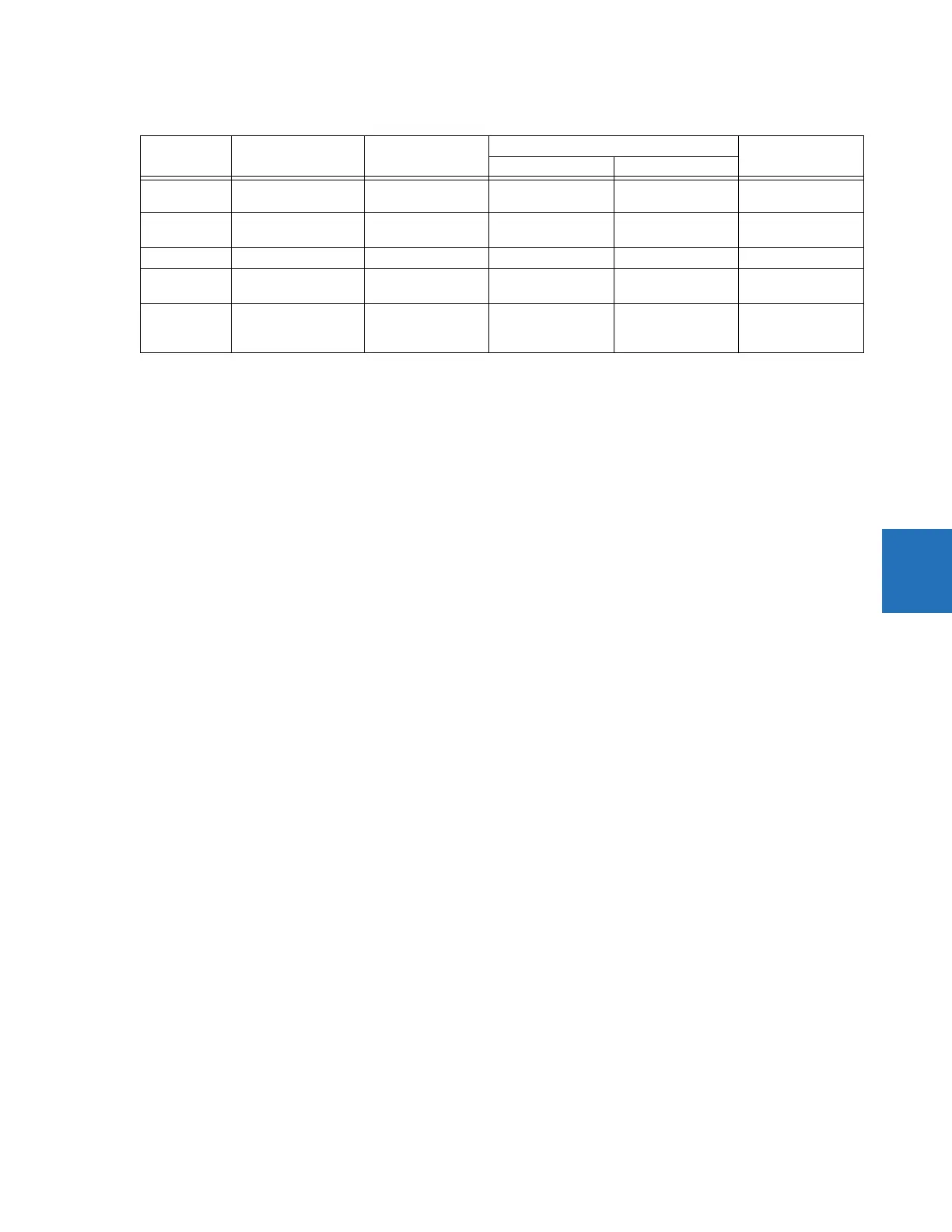
Number V1 or V2 (source Y) V2 or V1 (source Z) Auto-selected combination Auto-selected
voltage
Source Y Source Z
1 Phase VTs and
Auxiliary VT
Phase VTs and
Auxiliary VT
Phase Phase VAB
2 Phase VTs and
Auxiliary VT
Phase VT Phase Phase VAB
3 Phase VT Phase VT Phase Phase VAB
4 Phase VT and Auxiliary
VT
Auxiliary VT Phase Auxiliary V auxiliary
(as set for source Z)
5 Auxiliary VT Auxiliary VT Auxiliary Auxiliary V auxiliary
(as set for selected
sources)