5-364 L90 LINE CURRENT DIFFERENTIAL SYSTEM – INSTRUCTION MANUAL
CONTROL ELEMENTS CHAPTER 5: SETTINGS
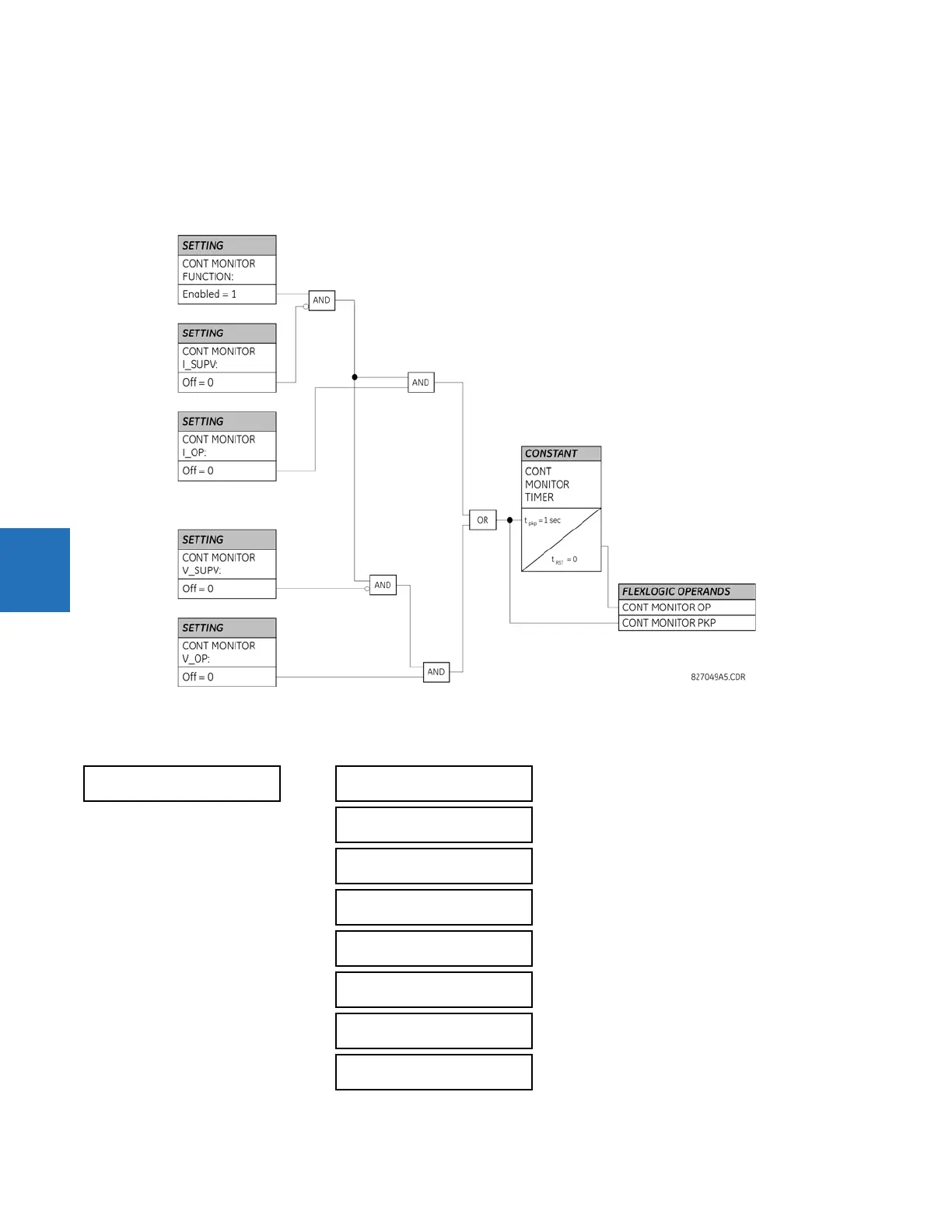
5
The continuous monitor logic is used to detect the operation of any tripping element that has operated under normal load
conditions; that is, when the disturbance detector has not operated. Because all tripping is supervised by the disturbance
detector function, no trip is issued under these conditions. This can occur when an element is incorrectly set so that it can
misoperate under load. The continuous monitor can detect this state and issue an alarm and/or block the tripping of the
relay.
Figure 5-208: Continuous monitor logic
5.8.11.6 CT failure detector
SETTINGS CONTROL ELEMENTS MONITORING ELEMENTS CT FAILURE DETECTOR 1(2 or 4)
CT FAILURE
DETECTOR 1
CT FAIL 1 FUNCTION:
Disabled
Range: Disabled, Enabled
CT FAIL 1 BLOCK:
Off
Range: FlexLogic operand
CT FAIL 1 3I0 INP 1:
SRC 1
Range: SRC 1, SRC 2, SRC 3, SRC 4
CT FAIL 1 3I0 INP 1
PKP: 0.2 pu
Range: 0.1 to 2.0 pu in steps of 0.1
CT FAIL 1 3I0 INP 2:
SRC 2
Range: SRC 1, SRC 2, SRC 3, SRC 4
CT FAIL 1 3I0 INP 2
PKP: 0.2 pu
Range: 0.1 to 2.0 pu in steps of 0.1
CT FAIL 1 3V0 INPUT:
SRC 1
Range: SRC 1, SRC 2, SRC 3, SRC 4
CT FAIL 1 3V0 INPUT
PKP: 0.20 pu
Range: 0.04 to 2.00 pu in steps of 0.01