CHAPTER 5: SETTINGS CONTROL ELEMENTS
L90 LINE CURRENT DIFFERENTIAL SYSTEM – INSTRUCTION MANUAL 5-373
5
I
n
is the measured overload RMS current at index n
E
n
is the accumulated energy at index n
E
n–1
is the accumulated energy at index n – 1
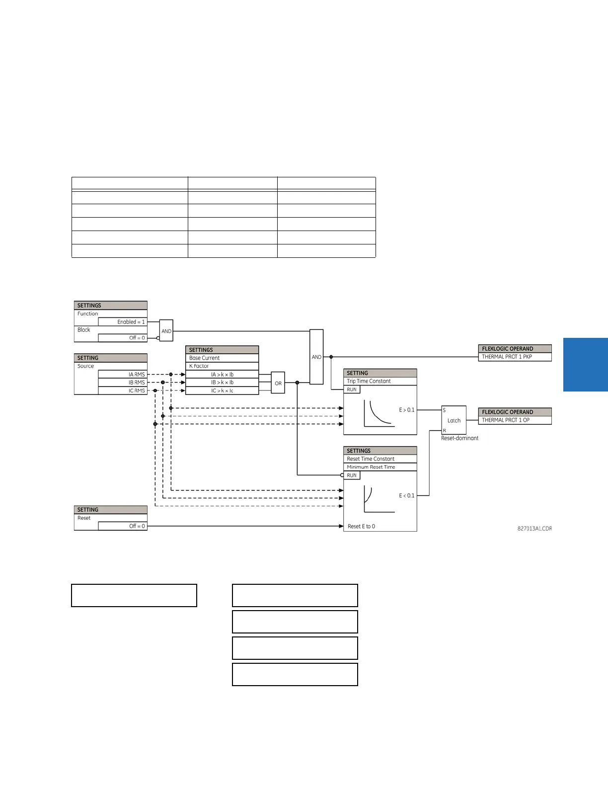
The thermal overload protection element removes the THERMAL PROT 1 OP output operand when E < 0.05. In case of
emergency, the thermal memory and THERMAL PROT 1 OP output operand can be reset using THERM PROT 1 RESET setting.
All calculations are performed per phase. If the accumulated energy reaches value 1 in any phase, the thermal overload
protection element operates and only resets when energy is less than 0.05 in all three phases.
Table 5-41: Typical time constants
The figure shows the logic for the thermal overload protection element.
Figure 5-214: Thermal overload protection logic
5.8.11.10 Broken conductor detection
SETTINGS CONTROL ELEMENTS MONITORING ELEMENTS BROKEN CONDUCTOR 1(2)
Protected equipment Time constant Minimum reset time
Capacitor bank 10 minutes 30 minutes
Overhead line 10 minutes 20 minutes
Air-core reactor 40 minutes 30 minutes
Busbar 60 minutes 20 minutes
Underground cable 20 to 60 minutes 60 minutes
BROKEN CONDUCTOR 1
BROKEN CONDUCTOR 1
FUNCTION: Disabled
Range: Disabled, Enabled
BROKEN CONDUCTOR 1
SOURCE: SRC 1
Range: SRC 1, SRC 2, SRC 3, SRC 4
BROKEN CONDUCTOR 1
I2/I1 RATIO: 20%
Range: 20.0% to 100.0% in steps of 0.1%
BROKEN CONDUCTOR 1
I1 MIN: 0.10 pu
Range: 0.05 to 1.00 pu in steps of 0.01
 Loading...


