6-28 L90 LINE CURRENT DIFFERENTIAL SYSTEM – INSTRUCTION MANUAL
METERING CHAPTER 6: ACTUAL VALUES
6
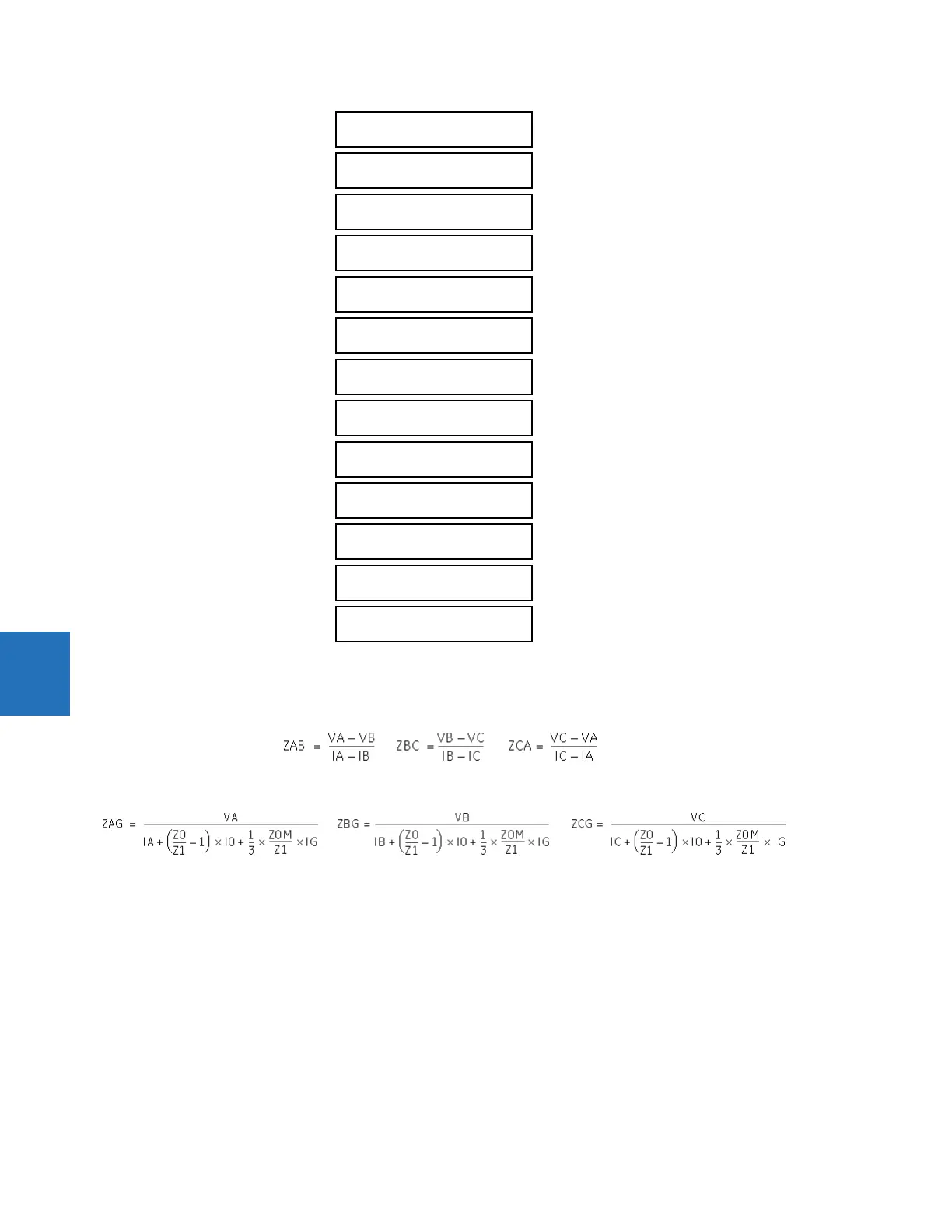
Loop impedance is defined as Z##=|Z##| Angle=R##+jX##, in secondary ohms and ## is the loop indication (AB, BC, CA,
AG, BG, and CG respectively).
They are calculated as
Eq. 6-5
per the following equations.
Eq. 6-6
where
VA, VB, VC are phase voltage phasors in secondary volts
IA, IB, IC are current phasors in secondary amps
I0 is the zero sequence current phasors in secondary amps
IG is the ground current from the parallel line scaled to the source phase CT in secondary amps
Z0/Z1 is the zero sequence impedance to positive sequence impedance ratio
Z0M/Z1 is mutual zero sequence impedance to positive sequence impedance ratio, both are settings taken from the first
enabled ground distance zone (count from zone 1 to zone 5)
ZAG, ZBG, ZCG are calculated only if at least one ground distance zone is enabled; otherwise all the metering quantities for
ground distance impedance (ZAG, ZBG, and ZCG) are reset to zero, including magnitude and angle. Note that VTs of the
distance source must be connected in Wye if the ground distance element is enabled.
CA LOOP IMPEDANCE
ANGLE: 0.00 DEG
AG LOOP RESISTANCE
RAG: 0.00 Ohms
AG LOOP REACTANCE
XAG: 0.00 Ohms
AG LOOP IMPEDANCE
ZAG: 0.00 Ohms
AG LOOP IMPEDANCE
ANGLE: 0.00 DEG
BG LOOP RESISTANCE
RBG: 0.00 Ohms
BG LOOP REACTANCE
XBG: 0.00 Ohms
BG LOOP IMPEDANCE
ZBG: 0.00 Ohms
BG LOOP IMPEDANCE
ANGLE: 0.00 DEG
CG LOOP RESISTANCE
RCG: 0.00 Ohms
CG LOOP REACTANCE
XCG: 0.00 Ohms
CG LOOP IMPEDANCE
ZCG: 0.00 Ohms
CG LOOP IMPEDANCE
ANGLE: 0.00 DEG