CHAPTER 10: THEORY OF OPERATION DISTANCE ELEMENTS
L90 LINE CURRENT DIFFERENTIAL SYSTEM – INSTRUCTION MANUAL 10-25
10
Phase distance fault type supervision can be enabled/disabled through SETTINGS GROUPED ELEMENTS SETTING
GROUP 1(6) DISTANCE PH DIST PH SELECT SUPV
and is applied to phase distance zone 1 to zone 3 only. G60 and L60
relays do not employ fault type supervision for the phase distance in all zones.
10.3.3.11 Zero-sequence directional characteristic
The extra zero-sequence characteristic applies to ground zones 2 and higher and is achieved by checking angles between:
• A ground element — I_0 × Z
D
and –V_0
• B ground element — I_0 × Z
D
and –V_0
• C ground element — I_0 × Z
D
and –V_0
The limit angle of the comparator is not adjustable and equals 90°. The zero-sequence directional characteristic improves
directional integrity for time-delayed operations after the memory expires.
10.3.3.12 Overcurrent supervision
The overcurrent supervision responds to the following currents:
• AB phase element — (I
A
– I
B
) /
• BC phase element — (I
B
– I
C
) /
• CA phase element — (I
C
– I
A
) /
• A, B, C ground element — | 3 × I_0 – 0.05 × I_1 |
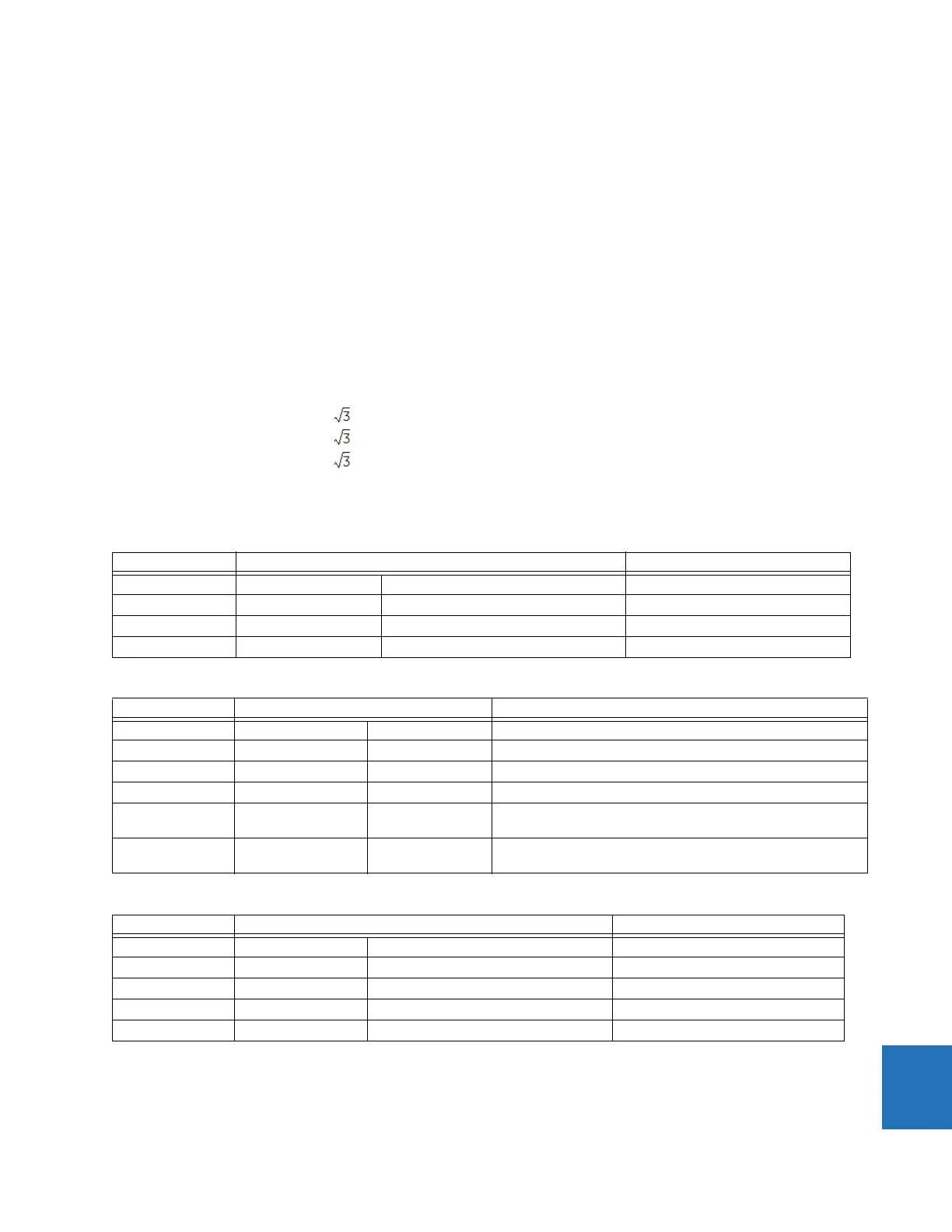
The following tables summarize the characteristics of the distance elements.
Table 10-1: Directional mho phase distance functions
Table 10-2: Directional mho ground distance functions
Table 10-3: Directional quadrilateral phase distance functions
Characteristic Comparator inputs Limit angle
Variable mho I × Z – V V_1M COMP LIMIT
Reactance I × Z – V I × ZCOMP LIMIT
Directional I × ZD V_1M DIR COMP LIMIT
Fault type NOT SLG See the Fault Type Characteristic section Removed during open pole conditions
Characteristic Comparator inputs Limit angle
Variable mho I × Z – V V_1M COMP LIMIT
Reactance I × Z – V I_0 × ZCOMP LIMIT
Directional I_0 × Z
D
V_1M DIR COMP LIMIT
Directional I_2 × Z
D
V_1M DIR COMP LIMIT (removed when 3I_0 > OC SUPV and I_2 < CUTOFF)
Fault-type I_0 I_2 50° (removed during open pole conditions or when 3I_0 > OC SUPV
and I_2 < CUTOFF)
Zero-sequence I_0 × Z
D
–V_0 90° (zones 2 and higher only; removed for zones 2 and higher
during open pole conditions)
Characteristic Comparator inputs Limit angle
Reactance I × Z – V I × ZCOMP LIMIT
Directional I × Z
D
V_1M DIR COMP LIMIT
Right Blinder I × Z
R
– V I × Z
R
90°
Left Blinder I × Z
L
– V I × Z
L
90°
Fault type NOT SLG See the Fault Type Characteristic section Removed during open pole conditions