Appendix B -Settings and Signals
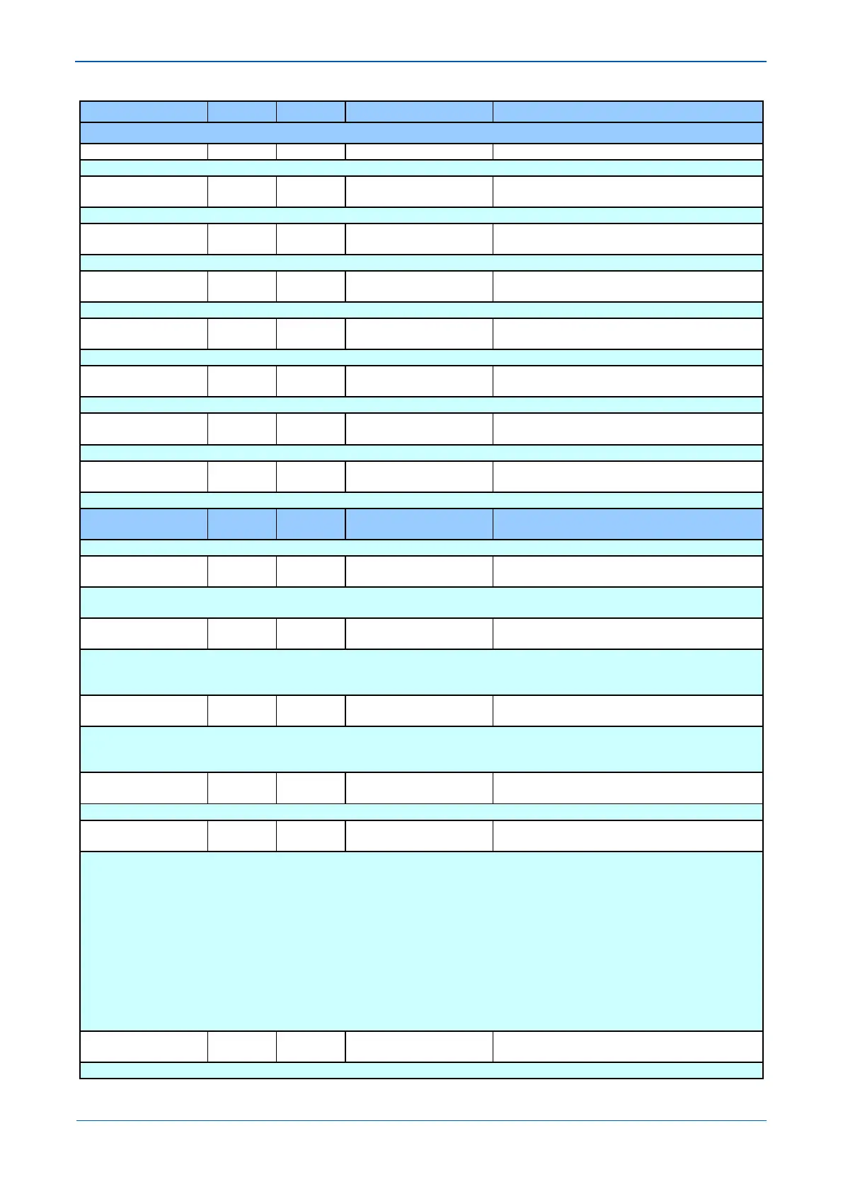
MENU TEXT COL ROW DEFAULT SETTING AVAILABLE OPTIONS
DESCRIPTION
Setting to allow Control Inputs 25 set/ reset.
Control Input 26 29 1A Control Input 26
From 32 to 163 in steps of 1
Setting to allow Control Inputs 26 set/ reset.
Control Input 27 29 1B Control Input 27
From 32 to 163 in steps of 1
[ASCII Text (16 chars)]
Setting to allow Control Inputs 27 set/ reset.
Control Input 28 29 1C Control Input 28
From 32 to 163 in steps of 1
[ASCII Text (16 chars)]
Setting to allow Control Inputs 28 set/ reset.
Control Input 29 29 1D Control Input 29
From 32 to 163 in steps of 1
[ASCII Text (16 chars)]
Setting to allow Control Inputs 29 set/ reset.
Control Input 30 29 1E Control Input 30
From 32 to 163 in steps of 1
[ASCII Text (16 chars)]
Setting to allow Control Inputs 30 set/ reset.
Control Input 31 29 1F Control Input 31
From 32 to 163 in steps of 1
[ASCII Text (16 chars)]
Setting to allow Control Inputs 31 set/ reset.
Control Input 32 29 20 Control Input 32
From 32 to 163 in steps of 1
[ASCII Text (16 chars)]
Setting to allow Control Inputs 32 set/ reset.
PARAMETERS
30 00
This column contains settings for Line Parameters
Line Length 30 01 100000
From 300 to 1000000 in steps of 10
[Courier Number (metres)]
Setting of the protected line/cable length in km. This setting is available if MEASURE’T SETUP column is selected as ‘Visible’ in the
CONFIGURATION column and if ‘Distance unit’ in the MEASURE’T SETUP column is selected as ‘kilometers’.
Line Length 30 02 62.1
From 0.05 to 621 in steps of 0.005
[Courier Number (miles)]
Setting of the protected line/cable length in miles. This setting is available if MEASURE’T SETUP column is selected as ‘Visible’ in the
CONFIGURATION column and if ‘Distance unit’ in the MEASURE’T SETUP column is selected as ‘miles’. Dual step size is provided, for
cables/short lines up to 10 miles the step size is 0.005 miles, 0.01 miles otherwise.
Line Impedance 30 03 10
From 0.05*v1/I1 to 500*V1/I1 in steps of 0.01*V1/I1
[Courier Number (impedance)]
Setting for protected line/cable positive sequence impedance in either primary or secondary terms, depending on the Setting Values
reference chosen in the CONFIGURATION column. The set value is used for Fault locator, and for all distance zone reaches calculation if
‘Simple’ setting mode under GROUP x DISTANCE SETUP is selected.
Line Angle 30 04 70
From 20 to 90 in steps of 1
[Courier Number (angle)]
Setting of the line angle (line positive sequence impedance angle).
kZN Res Comp 30 05 1
From 0 to 10 in steps of 0.01
[Courier Number]
Setting of the residual compensation factor magnitude, used to extend the ground loop reach by a multiplication factor of (1+ kZN), is
calculated as ratio:
│kZN│ = (Z0 – Z1)/3Z1 where,
Z1 = positive sequence impedance for the protected line or cable.
Z0 = zero sequence impedance for the protected line or cable.
This setting is a used for Distance protection (when set to simple mode) . If Distance protection is set to Advanced mode, there are individual
settings per Zone in the GROUP x DISTANCE ELEMENTS settings.
kZN Res Angle 30 06 0
From -180 to 90 in steps of 1
[Courier Number (angle)]
Setting of the residual compensation factor angle (in degrees) is calculated as:

 Loading...


