6-6 MIB High Impedance Bus Differntial Relay GEK-106426B
6.2 OUTPUTS AND LEDS CONFIGURATION 6 I/0 CONFIGURATION
6
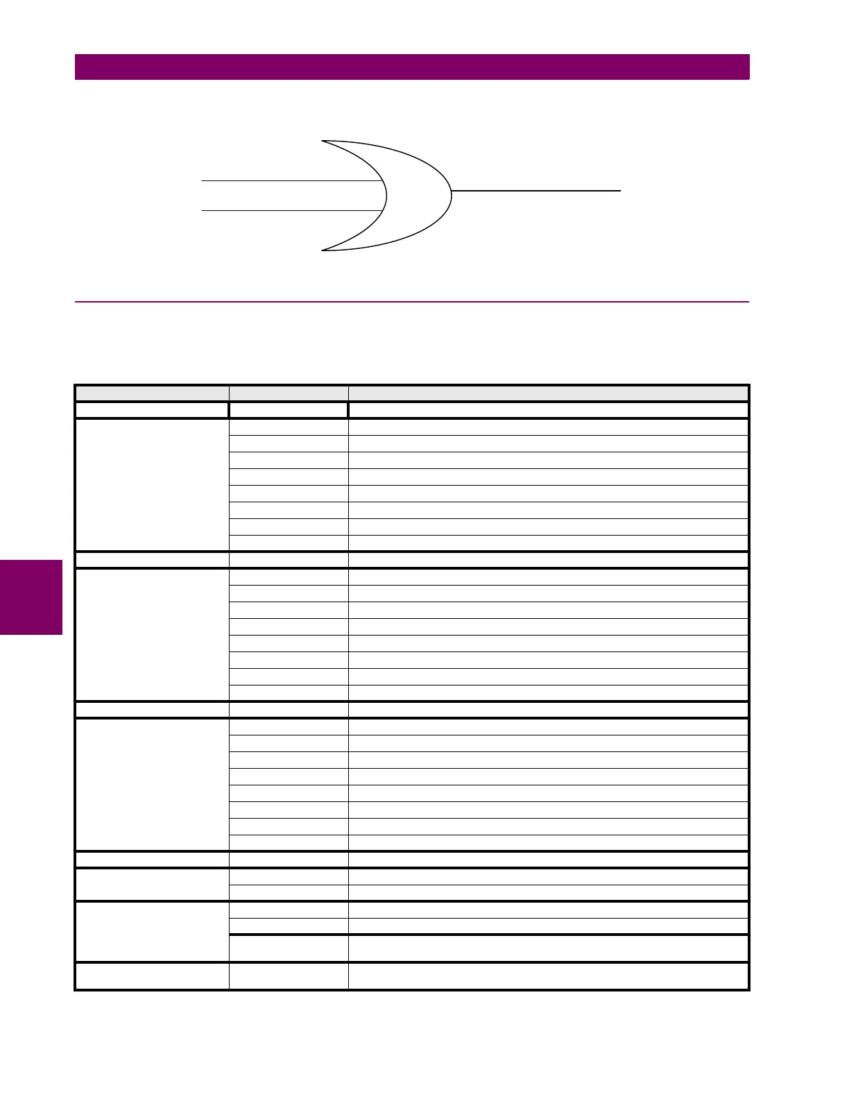
Elements from different groups cannot be included in an OR type logic.
6.2.2 OUTPUT AND LED ELEMENTS
The list of elements that can be assigned to the different outputs and LEDs is divided into the following groups:
GROUP FUNCTION DESCRIPTION
NO DEFINITION OUTPUT OR LED NOT ASSIGNED
TRIP 1
87 1 A Trip Trip of phase A first level differential function
87 1 B Trip Trip of phase B first level differential function
87 1 C Trip Trip of phase C first level differential function
87 1 Trip Trip of first level differential function (any phase)
87 2 A Trip Trip of phase A second level differential function
87 2 B Trip Trip of phase B second level differential function
87 2 C Trip Trip of phase C second level differential function
87 2 Trip Trip of second level differential function (any phase)
TRIP 2 General trip Trip of any of the above mentioned functions
PICKUP 1
87 1 A Pickup Pickup of phase A first level differential function
87 1 B Pickup Pickup of phase B first level differential function
87 1 C Pickup Pickup of phase C first level differential function
87 1 Pickup Pickup of first level differential function (any phase)
87 2 A Pickup Pickup of phase A second level differential function
87 2 B Pickup Pickup of phase B second level differential function
87 2 C Pickup Pickup of phase C second level differential function
87 2 Pickup Pickup of second level differential function (any phase)
PICKUP 2 General Pickup Pickup of any of the above mentioned functions
TRIP READY 1
87 1 A Virtual Trip Phase A first level differential function: there is a trip condition
87 1 B Virtual Trip Phase B first level differential function: there is a trip condition
87 1 C Virtual Trip Phase C first level differential function: there is a trip condition
87 1 Virtual Trip First level differential function (any phase): there is a trip condition
87 2 A Virtual Trip Phase A second level differential function: there is a trip condition
87 2 B Virtual Trip Phase B second level differential function: there is a trip condition
87 2 C Virtual Trip Phase C second level differential function: there is a trip condition
87 2 Virtual Trip High second differential function (any phase): there is a trip condition
TRIP READY 2 General Virtual Trip Virtual trip of any of the above mentioned functions
INPUTS / OUTPUTS
Input 1 Digital input 1
Input 2 Digital input 2
MIXED 1
86 Status Status of latching relay 86 (1=closed, 0=open)
EEPROM Failure Active when a failure is detected in EEPROM management
User settings Active when the default settings are active, not active when the user settings are
active
LEDs
Ready Active when the relay is READY and at least one function is enabled and has trip
enabled
OUTPUT/LED
87 1 Trip
87 2 Trip