A-4 MIB High Impedance Bus Differntial Relay GEK-106426B
A.2 COMMAND EXECUTION APPENDIX A
A
A.2.1 COMMAND STRUCTURE
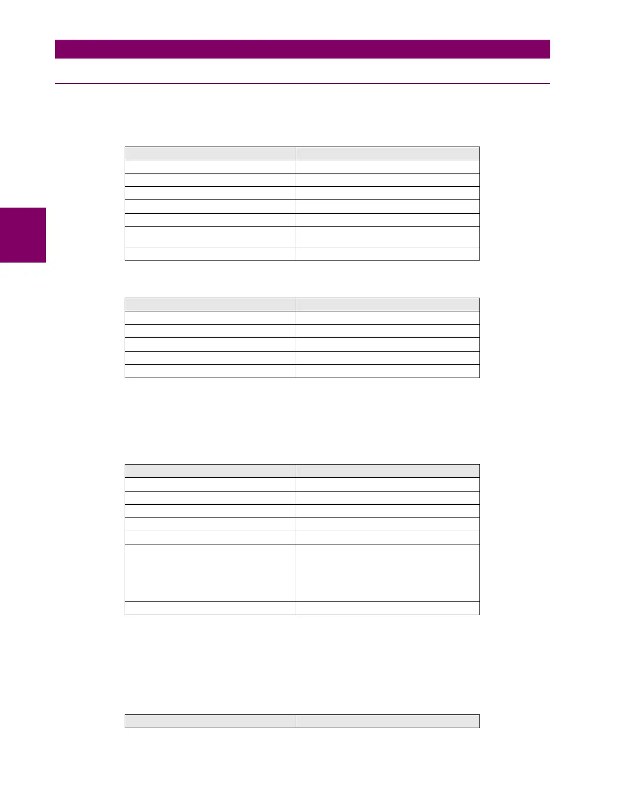
SELECTION:
Request:
Reply:
CONFIRMATION:
Request:
1 The registers sent correspond to two data: the command code in 16-bit integer format (2 bytes) and the relay
password in 32-bit integer format (4 bytes). The last one, when it is reordered from the least to the most weighted
byte, produces registers 2 and 3. For example: if the relay password is 27 (decimal), changed to hexadecimal it
results in 1B. In 32-bit it will be 00 00 00 1B. After reordering it, it becomes 1B 00 00 00, from where register 2 (1B
00) and 3 (00 00) are obtained.
2 Only for SET OPENINGS and Set I
2
in MIF module. The format is Float32. In the rest of cases this 4th register is not
used.
Reply:
FIELD LENGTH
Relay address 1 byte
Function 1 byte (10H)
Beginning address 1 word (000H) (High byte – low byte)
Number of registers 1 word (0001H) (High byte – low byte)
Number of bytes 1 byte (02H)
Value of the registers Register1=>Command code (Low byte – High
byte)
CRC 1 word
FIELD LENGTH
Relay address 1 byte
Function 1 byte (10H)
Beginning address 1 word (000H) (High byte – low byte)
No. of registers 1 word (0001H) (High byte – low byte)
CRC 1 word
FIELD LENGTH
Relay address 1 byte
Function 1 byte (10H)
Beginning address 1 word (0000H) (High byte – low byte)
Number of registers 1 word (0003H) (High byte – low byte)
Number of bytes 1 byte (06H)
Value of the registers Register1=>Command code (Low byte – High
byte).
Register2=>Relay password (Low byte – High
byte).
Register3=>Constant value 0000H
1
Register4=>Value (Low byte-High byte)
2
CRC 1 word
FIELD LENGTH