8-16 MIB High Impedance Bus Differntial Relay GEK-106426B
8.15 ACCEPTANCE TEST FOR HIGH IMPEDANCE MODULE 8 RELAY COMMISSIONING
8
Resistors Measure
Check that the resistor value between terminals is 2K:
NOTE: Accuracy of 12%.
C12 – D8
C11 – D7
C10 – D6
Thyrites current measure:
8.15.5 LATCHING RELAY
Contact test:
• Check with the external wiring diagram that all the auxiliary contacts of the latching relay are open and,
therefore, there is no continuity between them.
• Apply voltage to terminals +A1 y –A4 and verify that latching relay contacts operation time is below 25 ms.
• Verify that all auxiliary contacts have changed their position to closed and that there is continuity between each
pair of them.
• Apply voltage to terminals +B9 and –B12 and verify that latching relay contacts opening time is below 20 ms.
• Check that all auxiliary contacts have changed to their default position (open) and, therefore, there is no
continuity between each pair of them
Lamp:
• Apply the latching relay rated voltage to terminals CN-A6 and CN-A9 and check that the button lightens up.
• Switch the voltage off and check the lamp turns off.
• Press the button and check for continuity between CN-A7 and CN-A8
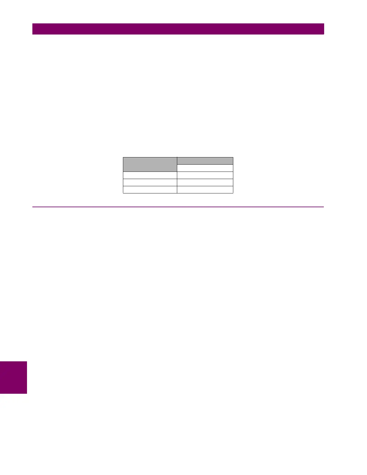
MOV TERMINALS
APPLIED VOLTAGE
290 VCA
C12-D4 2- 10 mA
C11-D3 2- 10 mA
C10-D2 2- 10 mA