3-2 MIB High Impedance Bus Differntial Relay GEK-106426B
3.2 HIGH IMPEDANCE MODULE DESCRIPTION 3 HARDWARE
3
3.2HIGH IMPEDANCE MODULE DESCRIPTION
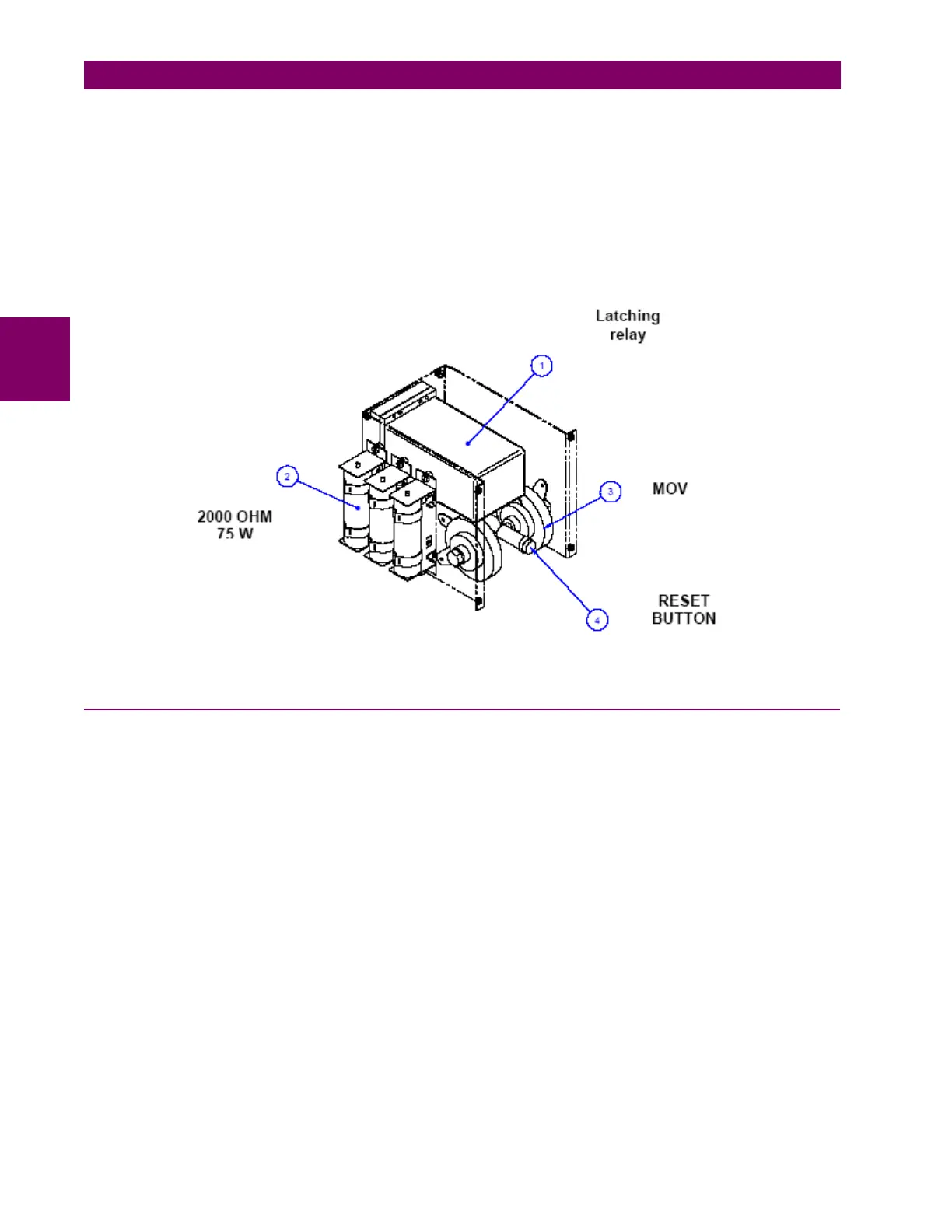
High impedance modules incorporate the following parts:
1. Latching relay
2. Resistors
3. MOV (Metal Oxide Varistors)
4. Reset button
Metallic Case
Figure 3–2: INTERNAL MOUNTING VIEW
3.2.1 MOUNTING
The HID module is composed of a black metallic stainless steel case. The case contains a metallic panel to which the
MOV (Metal Oxide Varistors) and the stabilizing resistors are hooked, as well as the connections base for the latching
relay and internal connections among the stabilizing resistors, MOV, and latching relay contacts.
Components are mounted on a base screwed to the rear side of the case. The module is closed with the frontal plate
where the latching relay reset button is located. This allows the user access to the front reset button. The HID module is
secured to the panel with the 4 M6 screws provided with the unit.