GEK-106426B MIB High Impedance Bus Differntial Relay A-19
APPENDIX A A.6 OSCILLOGRAPHY
A
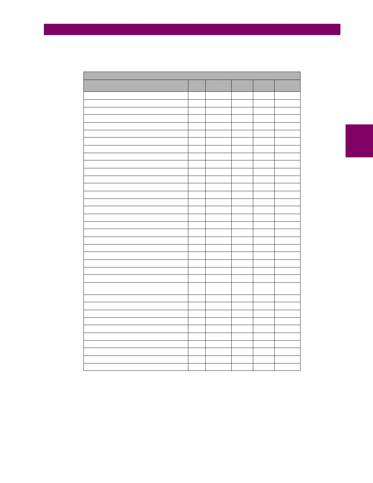
For the first block, that contains the analog and digital channels samples, the structure is as follows:
MIB
DESCRIPTION BIT # RECORD
INDEX
BIT
INDEX
#
BYTES
FORMAT
Id A 0 0 0 2 F2
Id B 16 1 0 2 F2
Id C 32 2 0 2 F2
87 1 A pickup 64 4 0 2 F4
87 1 B pickup 65 4 1 2 F4
87 1 C pickup 66 4 2 2 F4
87 1 pickup 67 4 3 2 F4
87 2 A pickup 68 4 4 2 F4
87 2 B pickup 69 4 5 2 F4
87 2 C pickup 70 4 6 2 F4
87 2 pickup 71 4 7 2 F4
General pickup 79 4 15 2 F4
87 1 Disable by input 83 5 3 2 F4
87 2 Disable by input 87 5 7 2 F4
Trip disable by input 95 5 15 2 F4
87 1 A trip 96 6 0 2 F4
87 1 B trip 97 6 1 2 F4
87 1 C trip 98 6 2 2 F4
87 1 trip 99 6 3 2 F4
87 2 A trip 100 6 4 2 F4
87 2 B trip 101 6 5 2 F4
87 2 C trip 102 6 6 2 F4
87 2 trip 103 6 7 2 F4
General trip 111 6 15 2 F4
Trip contact physical status (1=closed, 0=open) 120 7 8 2 F4
Alarm contact physical status (1=active=open,
0=not active=closed)
121 7 9 2 F4
Output 1 122 7 10 2 F4
Output 2 123 7 11 2 F4
Output 3 124 7 12 2 F4
Output 4 125 7 13 2 F4
Input 1 126 7 14 2 F4
Input 2 127 7 15 2 F4
86 Status 134 8 6 2 F4
Group change 137 8 9 2 F4
EEPROM failure 142 8 14 2 F4
User settings 143 8 15 2 F4