V 09/18
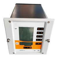
2 • Table of contents OptiStar CG06 Automatic gun control unit
Start-up and operation 27
OptiStar CG06 connections .................................................................................. 27
2.3 and 2.4 Aux connections ................................................................... 28
Connection guide ..................................................................................... 28
CG06 pin assignment .............................................................................. 29
CG06-C(F) pin assignment ...................................................................... 29
CG06-D(F) pin assignment ...................................................................... 29
Initial start-up ........................................................................................................ 30
Setting the device type ............................................................................ 30
Preparing the powder hopper/container .................................................. 30
Switch on the booth ................................................................................. 30
Daily start up ......................................................................................................... 30
Select the operating mode....................................................................... 30
Setting powder output and powder cloud ................................................ 31
OptiStar CG06 gun release ..................................................................... 32
Setting the electrode rinsing air ............................................................... 33
Setting the shaping air (optional) ............................................................. 33
Powder coating ........................................................................................ 34
Remote control by OptiSelect GM02 manual gun ................................... 34
Shut-down ............................................................................................... 34
Saving programs .................................................................................................. 34
Technical explanations concerning high voltage and spray current..................... 35
Characteristic curves of Preset mode ..................................................... 35
Characteristic curve of Program mode .................................................... 35
Additional functions 37
System parameters .............................................................................................. 37
Entering the system parameters ............................................................. 37
Exiting the system parameter mode ........................................................ 38
Trigger counter and software request .................................................................. 38
Keyboard lock ....................................................................................................... 38
Operation with other guns .................................................................................... 39
Configuration of the Tribo gun ................................................................. 39
Operation of the Tribo gun without adapter ............................................. 39
Powder output/powder hose correction ................................................................ 40
Carrying out a powder output correction ................................................. 40
Procedure (powder output correction) ..................................................... 40
Procedure (powder hose correction) ....................................................... 41
Example table for powder output/powder hose correction ...................... 41
Correction factor - diagram ...................................................................... 42
RAM reset ............................................................................................................. 42
Cleaning mode ..................................................................................................... 43
Options 45
FlowControl module .............................................................................................. 45
DigitalBus .............................................................................................................. 46
Controlling the OptiStar control units by a superordinated control unit ... 46
Structure of the 16 bit parallel bus ........................................................... 47
Command table and value ranges .......................................................... 48
Timing diagram ........................................................................................ 48
DigitalBus - allocation .............................................................................. 50
Digital Connector CD02 with connection designations ........................... 51
CAN bus ............................................................................................................... 51
Hardware ................................................................................................. 52
CAN bus cable - plug assignment ........................................................... 52
System release in network operation ...................................................... 53
Determining user address (Node-ID) and Baud rate ............................... 53