PART 2
AC GENERATORS
Page 24
Section 2.1
Description and Components
INTRODUCTION
The alternator contained within the generator is a revolving field
(rotor) type with a stationary armature (stator), and excitation
to the field provided through brushes and slip rings (direct
excitation). The generator may be used to supply electrical
power for the operation of the 120 and/or 240 VAC, 1-phase,
60 Hz, AC loads.
ENGINE-GENERATOR DRIVE SYSTEM
The air-cooled engine is directly coupled to the rotor internally.
Both the engine and the rotor operate at 3600 rpm to provide a
60 HZ AC output.
ALTERNATOR ASSEMBLY
The standard alternator consists of three basic components;
a rotor, stator, and brush assembly. The rotor assembly
provides the magnetic field which will induce a voltage into the
stator assembly. The brush assembly provides the electrical
connection to the rotor, which allows for excitation voltage and
current to create the needed magnetic field.
Rotor
Operating the 2-pole rotor at 3600 rpm will supply 60 HZ AC.
The term “2-pole” means the rotor has a single north and a
single south magnetic pole. Held in place with a single through
bolt, the tapered rotor shaft mounts to the tapered crankshaft
of the engine. As the rotor rotates its lines of magnetic flux cut
across the stator windings and induce a voltage into the stator
windings. The rotor shaft has a positive and negative slip ring,
with the positive slip ring nearest the lower bearing carrier. The
bearing is pressed onto the end of the rotor shaft.
Figure 14. Rotor
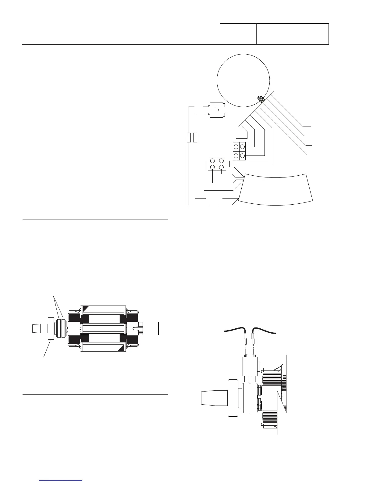
Stator
The stator houses a dual power winding and an excitation
winding. Coming from the stator there are eight stator leads as
shown in Figure 15.
An adapter molded into the engine block and a rear-bearing
carrier support the stator can. Four stator bolts connect the
rear bearing carrier and the stator can to the engine.
BLK
WHT
WHT
BLU
STATOR
RED
BLK
BA
RED(+)
WHT
AVR
C1
IC
IC
-
+
Figure 15. Stator Leads
BRUSH HOLDER AND BRUSHES
Attached to the lower bearing carrier, the brush holder and
brushes allow for electrical connection to the rotor. Positive
and negative brushes are retained in the brush holder, with the
positive brush riding on the slip ring nearest the rotor bearing.
The Red wire connects to the positive brush and the Black
Wire to the negative brush. The rotor windings receive rectified
and regulated field excitation voltage (DC) through the Red and
Black Wires. The current flow creates a magnetic field around
the rotor having a flux concentration that is proportional to the
amount of current flow on the Red and Black Wires.
BLACK
RED
-
+
Figure 16. Brush Holder and Brushes