PART 3
TRANSFER SWITCH
Page 46
Section 3.4
Diagnostic Tests
2. If the VOM indicated CONTINUITY, repair or replace the
wiring in the appropriate circuit.
TEST 38 – CHECK N1 AND N2 VOLTAGE
Discussion
Loss of utility source voltage to the generator will initiate a
startup and transfer by the generator. Testing at the control
panel terminal block will divide the system in two, thereby
reducing troubleshooting time.
Procedure
1. Set the AUTO-OFF-MANUAL switch to OFF.
2. Set a VOM to measure AC voltage.
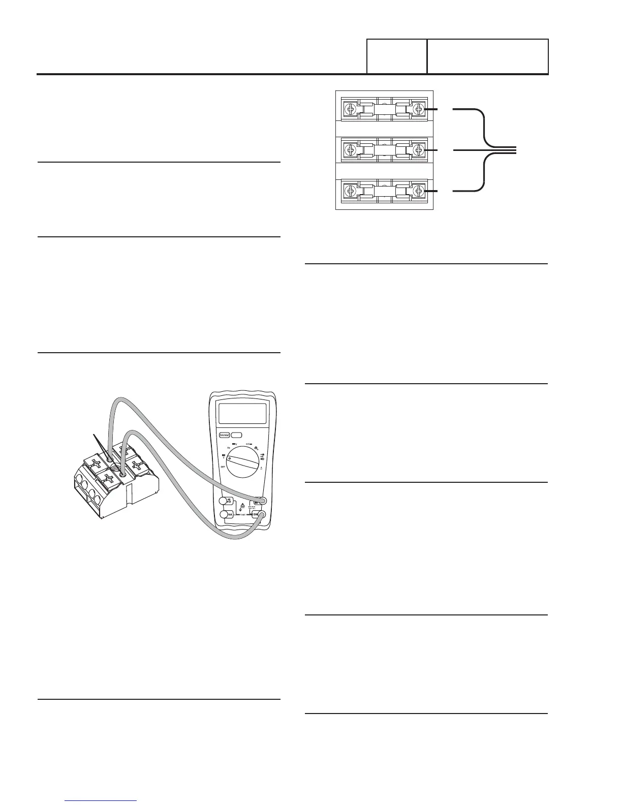
3. See Figure 30. Connect one test lead to Wire N1 at the
terminal block in the generator control panel. Connect the
other test lead to Wire N2. Utility line-to-line voltage should
be measured.
Results
Refer to Flow Chart
Figure 30. Terminal Block Test Points
TEST 39 – CHECK UTILITY SENSE VOLTAGE
The N1 and N2 terminals in the transfer switch deliver utility
voltage “sensing” to the controller. If voltage at the terminals
is zero or low, standby generator startup and transfer to the
“Standby” source will occur automatically as controlled by the
circuit board. A zero or low voltage at these terminals will also
prevent retransfer back to the “Utility” source.
Procedure
With utility source voltage available to terminal lugs N1 and N2,
use a VOM to test for utility source line-to-line voltage across
terminal locations N1 and N2 terminals. Normal line-to-line
utility source voltage should be indicated.
T1
N2
N1
Figure 31. Transfer Switch Fuse Block
Results
1. If voltage reading across the N1 and N2 terminals is zero
or low, refer to Flow Chart.
2. If voltage reading is good, refer to Flow Chart.
TEST 40 – CHECK UTILITY VOLTAGE AT
TRANSFER SWITCH
Procedure
1. Set a Volt-Ohm-Milliammeter (VOM) to measure AC
voltage.
2. Connect meter test leads across the Utility Disconnect
breaker in the transfer switch. Measure and record the
voltage.
Results
1. If the VOM indicated approximately 240 VAC, refer back to
flow chart.
2. If the VOM did not indicate 240 VAC, verify any additional
breakers or wiring are correct.
TEST 41 – CHECK UTILITY SENSING
VOLTAGE AT THE CONTROLLER
Discussion
If the generator starts and transfer to STANDBY occurs in the
automatic mode when acceptable UTILITY source voltage is
available at the terminal block, the next step is to determine if
sensing voltage is reaching the controller.
Note: The System Ready LED will flash in AUTO or UTILITY
LOST will display on the panel.
Procedure
1. Set the AUTO-OFF-MANUAL switch to OFF.
2. Disconnect the N1/N2 connector from the control panel
(see Figure 34).