AC GENERATORS
PART 2
Page 31
Section 2.4
Diagnostic Tests
Procedure
1. Locate and disconnect the Red Wire and the Black Wire
from the voltage regulator.
2. Set a Volt-Ohm-Meter (VOM) to measure resistance.
3. Connect one meter test lead to the Red brush wire and
connect the other meter test lead to the Black brush wire.
Measure and record the resistance.
4. Set VOM to measure DC voltage.
5. Connect one meter test lead to the positive post of the
battery and the other meter test lead to the negative post
of the battery. Measure and record the voltage indicated.
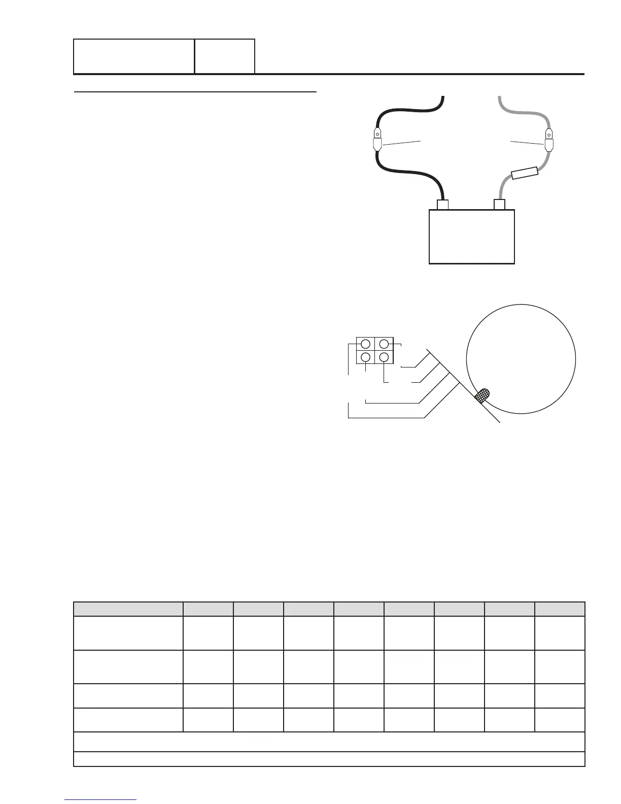
6. Using a jumper wire similar to Figure 20, connect a
jumper wire to the disconnected female connector Red
Wire and the positive post of the battery.
7. Using a jumper wire similar to Figure 20, connect a
jumper wire to the disconnected female connector Black
Wire and the negative post of the battery.
8. Disconnect the C1 connector from the voltage regulator
9. Set a VOM to measure AC voltage.
10. Connect meter test leads across C1 Terminals Points 1
(Blue Wire) and 2 (Blue Wire). Refer to Figure 21
11. Set the AUTO-OFF-MANUAL switch to the MANUAL
position.
12. Once the engine reaches rated speed, measure and
record the voltage.
13. Set the AUTO-OFF-MANUAL switch to the OFF position.
14. Connect meter test leads across points 3 (Green Wire)
and 4 (White Wire). Refer to Figure 21
15. Set the AUTO-OFF-MANUAL switch to the MANUAL
position.
16. Once the engine reaches rated speed, measure and
record the voltage.
17. Set the AUTO-OFF-MANUAL switch to the OFF position.
BATTERY
-
+
FUSE
MALE SPADE TERMINALS
BLACK WIRE
TO BRUSHES
RED WIRE
TO BRUSHES
(INSULATED)
(INSULATED)
5 AMP FUSE
Figure 20. Jumper Wires Connected
STATOR
C1
BLUE
WHITE
BLUE
GREEN
1
2
3
4
Figure 21. C1 Test Points
18. Remove the jumper wire that was connected in Step 5
from the Red Wire.
19. Set the VOM to measure DC amperage and re-locate the
test leads to the correct spot.
20. Connect the negative meter test lead to the disconnected
Red Wire (Female Side). Connect the positive meter test
lead to the positive post of the battery. Measure and
record the static DC amperage
Results: A B C D E F G H
Blue and Blue
Above 20
VAC
Above 20
VAC
Below 50
VAC
Zero or
Residual
Volts
Below 20
VAC
Below 50
VAC
Above 20
VAC
Below 20
VAC
White and Green
Above 20
VAC
Below 20
VAC
Above 50
VAC
Zero or
Residual
Volts
Below 20
VAC
Below 50
VAC
Above 20
VAC
Below 20
VAC
Static Rotor Amp Draw 0.22 - 0.46 0.22 - 0.46 0.22 - 0.46
Zero Current
Draw
Above 1 Amp 0.22 - 0.46
Zero Current
Draw
0.22 - 0.46
Running Rotor Amp Draw 0.22 - 0.46 0.22 - 0.46 0.22 - 0.46
Zero Current
Draw
Above 1 Amp 0.22 - 0.46
Zero Current
Draw
Above 1 Amp
Note: Actual values measured may vary by as much as .5 amps; depending on the type and quality of meter used, the condition of the unit, and how good the
connection is between the test leads and test points.
ç
MATCH RESULTS WITH LETTER AND REFER TO FLOW CHART IN SECTION 2.3 “Problem 1”
è
Table 2. Test 4 Results – Fixed Excitation Test