PART 2
AC GENERATORS
Page 32
Section 2.4
Diagnostic Tests
21. Set the AUTO-OFF-MANUAL switch to the MANUAL
position.
22. Measure and record the running DC amperage.
23. Set the AUTO-OFF-MANUAL switch to the OFF position
and reconnect the wires to the voltage regulator.
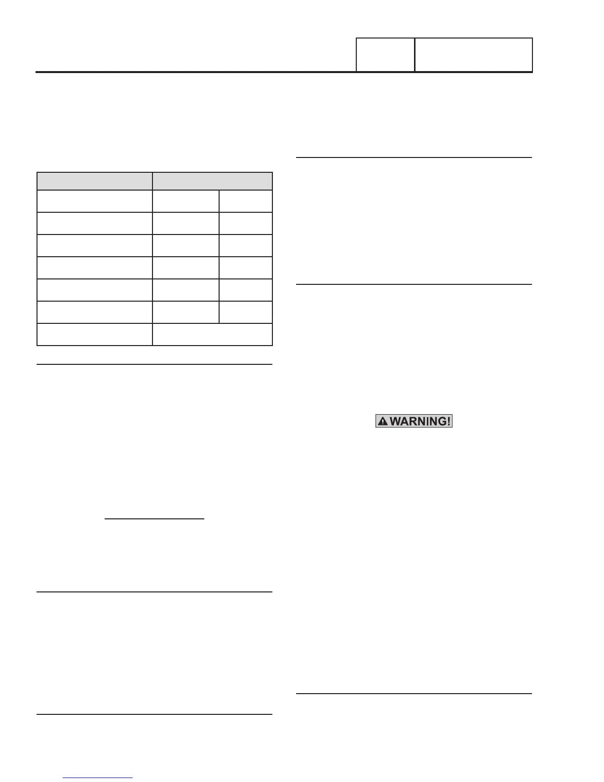
Table 3. Test 4 Results Worksheet
Test Point Results
Rotor Resistance
Ohms
Battery Voltage
VDC
Blue to Blue Voltage
VAC
White and Blue Voltage
VAC
Static Rotor Amp Draw
Amps
Running Rotor Amp Draw
Amps
Column Identified
Results
1. Using the values recorded in the above procedures,
compare the results to Table 2 “Test 4 Results – Fixed
Excitation Test”. Determine the appropriate lettered
column to use and refer back to the flow chart. The
rotor amp draws are a calculated amp draw and actual
amperage readings may vary depending on the resistance
of the rotor and battery voltage.
Note: To calculate rotor amp draw take the battery voltage
applied, divided by the actual resistance reading of the
rotor. Rotor resistance can be measured between the RED
and BLACK wires going to the voltage regulator.
12.9VDC
50 Ohms x .258 DC Amps
TEST 6 – RESISTANCE CHECK OF ROTOR
CIRCUIT
Procedure
1. Locate and disconnect the Red and Black wires from the
voltage regulator.
2. Set a Volt-Ohm-Milliammeter (VOM) to measure
resistance.
3. Connect meter test leads across the female Red and Black
wires at connector disconnected in Step 1. Measure and
record the resistance.
Results
1. If the VOM indicate a resistance of approximately 40
ohms ± 20 ohms, verify rotor amp draw.
2. If the VOM did not indicate the proper resistance, refer
back to flow chart.
TEST 7 – CHECK BRUSHES AND SLIP RINGS
Discussion
The brushes and slip rings function to provide an electrical
connection for excitation current from the stationary
components to the rotating rotor. Made of a special long
lasting material, brushes seldom wear out or fail. However,
slip rings can develop a tarnish or film that can inhibit or offer
a resistance to the flow of current. Such a non-conducting
film usually develops during non-operating periods. Broken or
disconnected wiring can also cause loss of excitation current
to the rotor.
Procedure
1. Disassemble the Generator until the brushes and slip rings
are exposed. Refer to Section 5.1 “Major Disassembly.”
2. Inspect the brush wires and verify they are secured and
properly connected.
3. Inspect the brush assembly for excessive wear, or
damage.
4. Inspect the rotor slip rings. If their appearance is dull or
tarnished, polish with a fine grade abrasive material.
Do not use metallic grit to polish slip rings. This may
cause irreversible damage to the rotor.
5. The Black Wire, located on the negative brush terminal,
provides an electrical connection to the voltage regulator.
To test this wire for an OPEN condition, remove the Black
Wire from the brush assembly.
6. Set Volt-Ohm-Milliammeter (VOM) to measure resistance.
7.
C
onnect one meter test lead to the Black Wire at the brush
assembly and connect the other meter test lead to the
Black wire at the voltage regulator.
•If the VOM indicated INFINITY, repair or replace the Black
Wire between the negative slip ring and the voltage regulator.
•If the VOM indicated CONTINUITY, continue to Step 8.
8. Disconnect the Red Wire from the brushes.
10. Connect one meter test lead to the Red Wire disconnected
at the brushes and the other meter test lead to the Red
wire disconnected at the voltage regulator.
Results
1. Repair, replace, or reconnect wires as necessary.
2. Replace any damage slip rings or brush holder.
3. Clean and polish slip rings as required.