ENGINE/DC CONTROL
PART 4
Page 55
Section 4.3
Operational Analysis
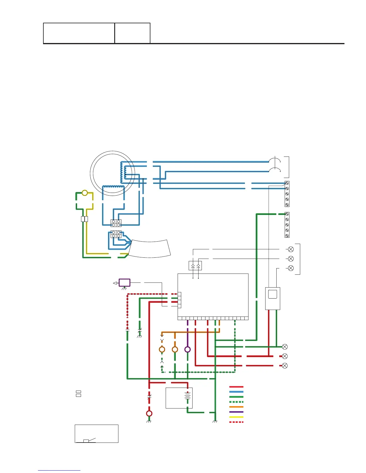
= 12 VDC ALWAYS PRESENT
= AC VOLTAGE
= GROUND
= 12 VDC DURING CRANKING ONLY
= 12 VDC DURING ENGINE RUN CONDITION
= DC FIELD EXCITATION
= 5 VDC
= PCB GROUND CONTROL
RED(+)
WHT
C1
IC
IC
INPUT
UTILITY
240 VAC
TRANSFER
+ BATTERY
GROUND
56015B23
23
0
0
BLK
0
56
RED
FS
16
13
SC
0
86
85
HTO
LOP
18
WHT
WHT
CB
15B
14
BLK
RED
BLK
12V
BATTERY
SC
0
CS
IM
SP
21
N2
N1
18
13
86
85
4
3
2
1
J1
CONTROLLER
J2
18171615141312109 1186 743 5
SM
GROUND
NEUTRAL
STATOR
WHT
BLK
WHT
BLU
WHT
GRN
BLUBLU
BLK
BA
RED
BC
RED
WIRE
+
BLK
WIRE
-
0
0
0
SUPPLIED
CUSTOMER
OUTPUT
GENERATOR
240 VAC
1
2
N1
N2
N1
1
2
CB - CIRCUIT BREAKER,
MAIN OUTPUT
GND - GROUND
HTO - HIGH TEMPERATURE SWITCH
IM - IGNITON MODULE
LOP - LOW OIL PRESSURE SWITCH
SC - STARTER CONTACTOR
SM - STARTER MOTOR
SP1 - SPARK PLUG
- SPLICE
- SPLICE INTERCONNECT
IC
BC - BATTERY CHARGER
C1 - 4 POS. CONNECTOR
LEGEND
BA - BRUSH ASSEMBLY
AWG SIZE
12
SHOWN OTHERWISE
300V UL LISTED UNLESS
NOTE: ALL WIRES 18 AWG
90
90
N1
N2
T1
RED
WHT
RED
BLK
YLW
YLW
AVR
UTILITY FAILURE AND ENGINE CRANKING
When the utility sensing voltage drops out the controller will start a 10 second timer. If the voltage does not return fully of is below
60 percent of normal the generator will start to crank.
The controller action delivers 12 VDC to the starter contactor via wire 56. When the starter contactor energizes, it delivers battery
voltage to the starter motor and the engine will crank.
Wire 56 also delivers 12 VDC to the choke solenoid. The controller action grounds wire 90 to actuate the choke solenoid cyclically
during cranking. The controller action will remove wire 90 from ground during normal running operation.
The controller delivers 12 VDC to the fuel solenoid during cranking and will continue to during normal running operation.
As the engine cranks a magnet on the flywheel induces a high voltage into the engines ignition magneto (IM). A spark is produced
that jumps the spark plug gap.
During cranking residual magnetism from the rotor induces a voltage into the stator (blue) excitation wires and the (green and white)
sensing wires. Voltage from the excitation wires power up the voltage regulator.