EasyManua.ls Logo

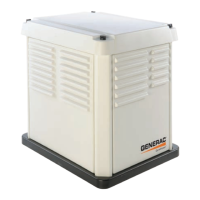
Generac Power Systems CorePower

Generac Power Systems CorePower
116 pages
To Next Page IconTo Next Page
Loading...
DIAGNOSTIC
REPAIR
MANUAL
STANDBY GENERATORS
CorePower Home Standby Generator
MODELS:
6/7 kW
®

Table of Contents

Questions and Answers:

Generac Power Systems CorePower Specifications

General IconGeneral
Fuel TypeGasoline
Rated AC Voltage120 / 240 V
Frequency60 Hz
Wheel KitIncluded
Engine TypeOHV
Outlet Types(1) 120/240V L14-30R

Summary

PART 1 - GENERAL INFORMATION

Section 1.1 - Generator Basics

Covers fundamental generator principles, including parts and identification.

Section 1.2 - Measuring Electricity

Explains how to use meters to measure AC/DC voltage, frequency, current, and resistance.

Section 1.3 - Preparation Before Use

Details essential steps before generator operation, including fuel system configuration.

Section 1.4 - Operating Instructions

Provides guidance on using the control panel, automatic, and manual operation modes.

Section 1.5 - Automatic Operating Parameters

Defines parameters for automatic operation, including utility failure and cranking sequences.

Section 1.6 - General Maintenance

Outlines routine maintenance tasks for engine oil, air filter, spark plugs, and visual inspection.

Section 1.7 - General Troubleshooting

Covers general troubleshooting tips, recommended tools, and common issues.

PART 2 - AC GENERATORS

Section 2.1 - Description and Components

Details the AC alternator assembly, rotor, stator, and brush components.

Section 2.2 - Operational Analysis

Explains generator startup, on-speed operation, field excitation, and AC power output.

Section 2.3 - Troubleshooting Flowcharts

Provides step-by-step flowcharts for diagnosing common AC generator issues.

Section 2.4 - Diagnostic Tests

Details specific tests for diagnosing AC generator problems like voltage and frequency issues.

PART 3 - TRANSFER SWITCH

Section 3.1 - Description and Components

Describes the transfer switch, enclosure, EZ Transfer Operator, and fuse holder.

Section 3.2 - Operational Analysis

Explains the operational states: utility voltage present, transfer to standby, and transfer to utility.

Section 3.3 - Troubleshooting Flowcharts

Presents flowcharts for troubleshooting common transfer switch problems.

Section 3.4 - Diagnostic Tests

Details tests for diagnosing transfer switch issues, including voltage and wiring checks.

PART 4 - ENGINEDC CONTROL

Section 4.1 - Description and Components

Covers DC control system components: terminal strip, controller, switch, and fuse.

Section 4.2 - Engine Protective Devices

Details engine alarms like low oil pressure, high temperature, over speed, and low battery warnings.

Section 4.3 - Operational Analysis

Explains generator operation during utility source availability and failure.

Section 4.4 - Troubleshooting Flowcharts

Provides flowcharts for troubleshooting engine issues like not cranking or starting.

Section 4.5 - Diagnostic Tests

Details tests for diagnosing engine and DC control system faults.

PART 5 - DISASSEMBLY

Section 5.1 - Major Disassembly

Step-by-step instructions for disassembling the generator unit.

Section 5.2 - Exploded Views

Illustrates the generator components with part identification.

PART 6 - ELECTRICAL DATA

Wiring Diagram

Presents the overall wiring diagram for the generator system.

Electrical Schematic

Provides a detailed electrical schematic of the generator's circuitry.

Electrical Formulas

Lists common electrical formulas used for calculations and analysis.

APPENDIX A - SUPPLEMENTAL WORKSHEETS

APPENDIX B - INDEX OF FIGURES AND TABLES

Index of Figures

An alphabetical listing of all figures within the manual.

Index of Tables

An alphabetical listing of all tables within the manual.

Related product manuals