PART 4
ENGINE/DC CONTROL
Page 68
Section 4.5
Diagnostic Tests
•Maximum gaseous fuel pressure at the generator fuel inlet
connection is 7 inches water column for natural gas or 12
inches water column for LP gas.
•When propane gas is used, only a “vapor withdrawal” sys-
tem may be used. This type of system utilizes the gas that
forms above the liquid fuel. The vapor pressure must be high
enough to ensure engine operation.
•The gaseous fuel system must be properly tested for leaks
following installation and periodically thereafter. No leakage is
permitted. Leak test methods must comply strictly with gas
codes.
DANGER! Gaseous fuels are highly explosive. Do not
use flame or heat to test the fuel system for leaks.
Natural gas is lighter than air, and tends to settle in
high places. LP (propane) gas is heavier than air, and
tends to settle in low areas. Even the slightest spark
can ignite these gases and cause an explosion.
Procedure
A water manometer or a gauge that is calibrated in “ounces per
square inch” may be used to measure the fuel pressure. Fuel
pressure at the inlet side of the fuel solenoid valve should be
between 5-7 inches water column for natural gas (NG) or 10-12
inches water column for LP gas.
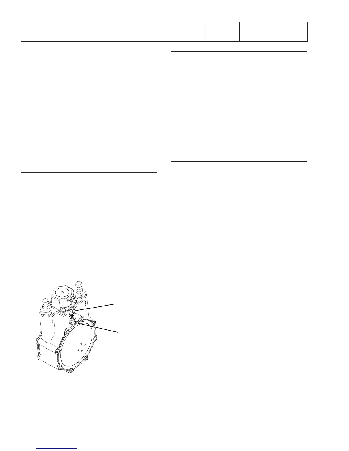
1. See Figure 47 for the gas pressure test point on the fuel
regulator. The fuel pressure can be checked at Port 1.
2. With the manometer connected properly, crank the engine.
Nominal fuel pressure should be measured. If pressure is
not measured while cranking refer back to flow chart.
Note: Where a primary regulator is used to establish fuel
inlet pressure, adjustment of that regulator is usually the
responsibility of the fuel supplier or the fuel supply system
installer.
PORT 1
PORT 2
Figure 47. Gas Pressure Test point
Results
1. If fuel supply and pressure are adequate, but engine will
not start refer back to flow chart.
2. If generator starts but runs rough or lacks power, repeat
the above procedure with the generator running and under
load. The fuel system must be able to maintain 10-12
inches water column at all load requirements for propane,
and 5-7 inches water column for natural gas. If proper
fuel supply and pressure is maintained, refer to Problem
18 Flow Chart.
TEST 61 – CHECK CIRCUIT BOARD WIRE 14
OUTPUT
Discussion
During any crank cycle, the controller’s crank relay and
run relay both energize simultaneously. When the run relay
energizes, it’s contacts close and 12 VDC is delivered to Wire
14 and to a fuel solenoid. The solenoid energizes open to allow
fuel flow to the engine. This test will determine if the controller
is working properly.
Procedure
1. Set AUTO-OFF-MANUAL switch to OFF.
2. Set a VOM to measure DC voltage.
3. Disconnect Wire 14 from the fuel solenoid.
4. Connect the positive test lead to disconnected Wire 14
and the negative test lead to a clean frame ground.
5. Set the AUTO-OFF-MANUAL switch to the MANUAL
position.
6. Battery voltage should be measured. If battery voltage is
measured, refer back to flow chart.
Note: Disconnect the 7.5 amp fuse before disconnecting
the J2 connector.
7. Disconnect the J2 connector from controller.
8. Set VOM to measure resistance.
9. Connect the positive test lead to disconnected Wire 14
and the negative test lead to J2 Pin 3 (Wire 14).
10. CONTINUITY should be measured. If CONTINUITY is not
measured, repair or replace Wire 14 between J2 Pin 3 and
the fuel solenoid.
Results
Refer to flow chart.