TRANSFER SWITCH
PART 3
Page 41
INTRODUCTION
Use the “Flow Charts” in conjunction with the detailed instructions in Section 3.4. Test numbers used in the flow charts correspond
to the numbered tests in Section 3.4. The first step in using the flow charts is to identify the correct problem on the following pages.
For best results, perform all tests in the exact sequence shown in the flow charts.
Section 3.3
Troubleshooting Flowcharts
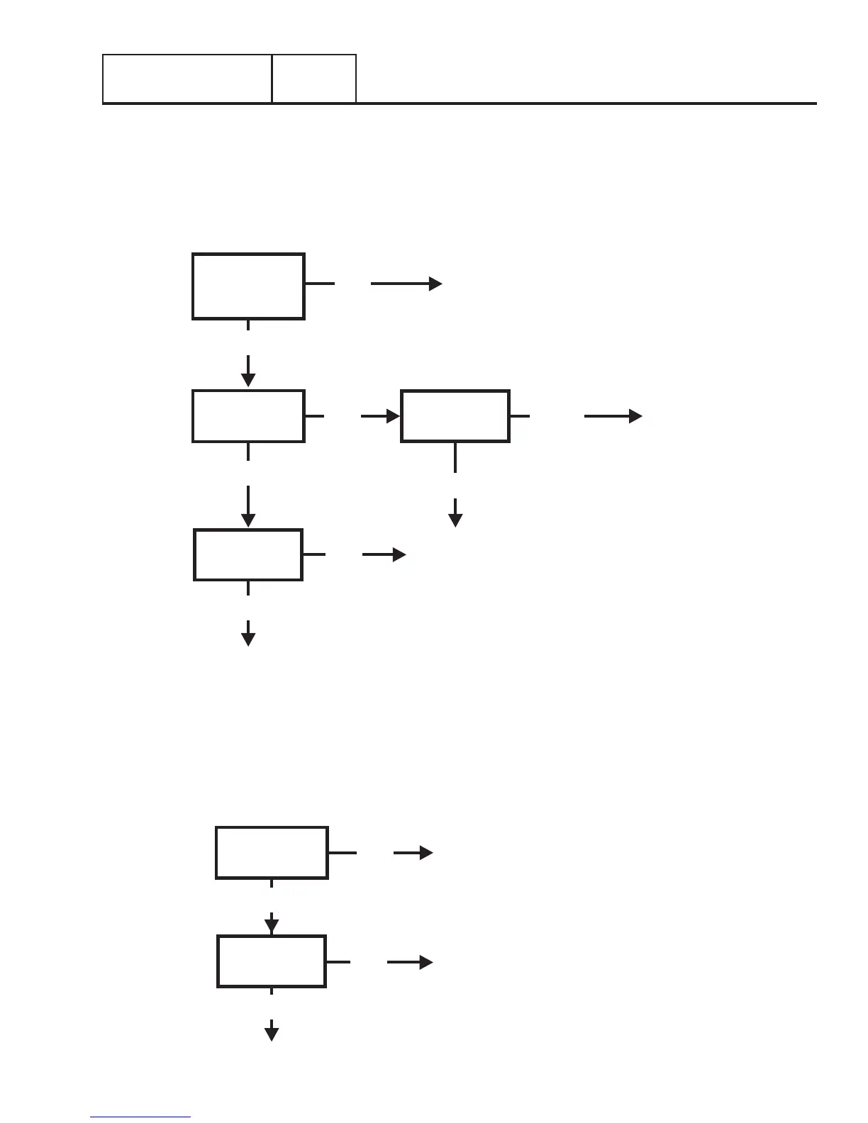
Problem 11 – In Automatic Mode, Generator Starts When Loss of Utility Occurs, Generator
Shuts Down When Utility Returns But There Is No Retransfer To Utility Power
OR
Generator Transfers to Standby During Excercise or in Manual Mode
REPAIR OR REPLACE AS NEEDED
RE-TEST
GOOD
GOOD
BAD
BAD
TEST 28 – TEST
TRANSFER
OPERATOR
TEST 30 –
CHECK WIRE 23
CIRCUIT
REPLACE
TRANSFER
OPERATOR
BAD
REPLACE
TRANSFER
OPERATOR
REPLACE
CONTROLLER
GOOD
GOOD
FIND CAUSE OF NO AC OUTPUT TO
TRANSFER SWITCH FROM GENERATOR
TEST 27 – CHECK
VOLTAGE AT
TRANSFER
SWITCH
TEST 28 – TEST
TRANSFER
OPERATOR
TEST 30 –
CHECK WIRE 23
CIRCUIT
TEST 29 –
CHECK WIRE
15B/194 CIRCUIT
REPAIR OR
REPLACE AS
NEEDED
BAD
BAD
BAD
GOOD
Problem 10 – In Automatic Mode, No Transfer to Standby
GOOD