ENGINE/DC CONTROL
PART 4
Page 69
Section 4.5
Diagnostic Tests
TEST 62 – CHECK FUEL SOLENOID
Discussion
In Test 61, if battery voltage was delivered to Wire 14, the
fuel solenoid should have energized open. This test will verify
whether or not the fuel solenoid is operating.
Fuel Solenoid FS1 Nominal Resistance – 14-16 ohms.
Procedure
1. Install a manometer to Port 2 on the fuel regulator. See
Figure 47.
2. Set the AUTO-OFF-MANUAL Switch to MANUAL.
3. Proper gas pressure should be measured during cranking.
If gas pressure is measured, the fuel solenoid is operating.
If gas pressure is not measured, repair or replace the fuel
solenoid.
Results
Refer to flow chart.
TEST 63 – CHECK CHOKE SOLENOID
Discussion
The automatic choke cycles open and closed during cranking
and remains de-energized in the open position during running.
Procedure
1. Turn off the fuel supply to the generator.
2. Set the AUTO-OFF-MANUAL Switch to the MANUAL
position.
3. While cranking the choke solenoid should energize and
pull the choke plate closed and release back to the open
position as the solenoid cycles during cranking. If the
choke solenoid does not cycle, verify that the choke
can be manually closed. There should be no binding or
interference.
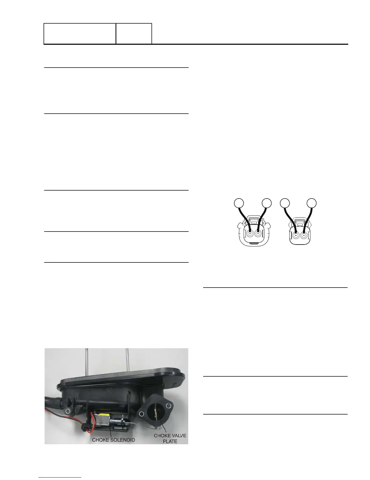
Figure 48. Choke Solenoid and Choke Valve Plate
4. Disconnect the Choke Solenoid Connector.
5. Set a VOM to measure DC voltage.
6. Connect the positive (+) test lead to Wire 56 (Pin 1)
of the connector going to the controller (Female Side)
Connect the negative (-) test lead to Wire 90 (Pin 2).
7. Set the AUTO-OFF-MANUAL Switch to MANUAL. While
cranking, battery voltage should be measured . If battery
voltage was not measured, verify continuity of Wire 90
between the Choke Solenoid Connector and J2-15 (Wire
90) at the controller. Verify continuity of Wire 56 between
the Choke Solenoid Connector Wire 56 and J2-11 (Wire
56). Repair or replace any wiring as needed.
8. Set a VOM to measure resistance.
9. Connect the positive (+) test lead to Wire 56 (Pin 1) of
Choke Solenoid Connector going to the choke solenoid
(Male Side). Connect the negative (-) test lead to Wire 90
(Pin 2). Approximately 3.7 ohms should be measured.
FEMALE SIDE
MALE SIDE
2 1
1 2
90
9056
56
Figure 49. Choke Solenoid Connector
Results
1. If battery voltage was not measured in Step 7 and wire
continuity is good, replace the controller.
2. If Choke Solenoid coil resistance is not measured in Step
9, replace the Choke Solenoid.
3. If battery voltage was not measured in Step 4, replace the
controller.
TEST 64 – CHECK FOR IGNITION SPARK
Discussion
If the engine cranks but will not start, perhaps an ignition
system failure has occurred. A special “spark tester” is required
to check for ignition spark.
Procedure
1. Remove spark plug lead from the spark plug.
2. Attach the clamp of the spark tester to the engine
cylinder head.
3. Attach the spark plug lead to the spark tester terminal.