PART 4
ENGINE/DC CONTROL
Page 72
Section 4.5
Diagnostic Tests
•Blown or leaking cylinder head gasket
•Improperly seated or sticking-valves
•Worn piston rings or cylinder. ( This will also result in a high
oil consumption)
The minimum allowable compression pressure for a cold engine
is 60 PSI. Compression values are difficult to obtain accurately
without special equipment. For this reason, compression
values are not published for the larger engines. However,
testing has proven that an accurate indication of compression in
the cylinder can be obtained by using the following procedure.
Note: Refer to Manufacturer's instructions for variations of
this procedure.
Procedure
1. Remove the spark plug.
2. Insert a compression gauge into the cylinder.
3. Crank the engine until there is no further increase in
pressure.
4. Record the highest reading obtained.
5. Repeat the procedure for the remaining cylinder and
record the highest reading.
Results
The minimum allowable compression pressure for a cold
engine is 60 PSI. If compression is poor, look for one or more
of the following causes:
•Loose cylinder head bolts
•Failed cylinder head gasket
•Burned valves or valve seats
•Insufficient valve clearance
•Warped cylinder head
•Warped valve stem
•Worn or broken piston ring(s)
•Worn or damaged cylinder bore
•Broken connecting rod
•Worn valve seats or valves
•Worn valve guides
TEST 67 – CHECK IGNITION COIL
Discussion
The ignition system is a solid-state (breakerless) type. The
system utilizes a magnet on the engine flywheel to induce a
relatively low voltage into an ignition coil assembly. Ignition
coil internal components increase the voltage and deliver the
resulting high voltage across the spark plug gap.
The ignition coil houses a solid-state circuit that controls
ignition timing. Timing is fixed, air gap is non-adjustable and
spark advance is automatic.
Major components of the ignition system include (a) the ignition
coil assembly, (b) the spark plug, and (c) the engine flywheel.
Solid-state components encapsulated in the ignition coil are not
accessible and cannot be serviced. If the coil is defective, the
entire assembly must be replaced. The air gap between the coil
and the flywheel magnet is fixed and non-adjustable.
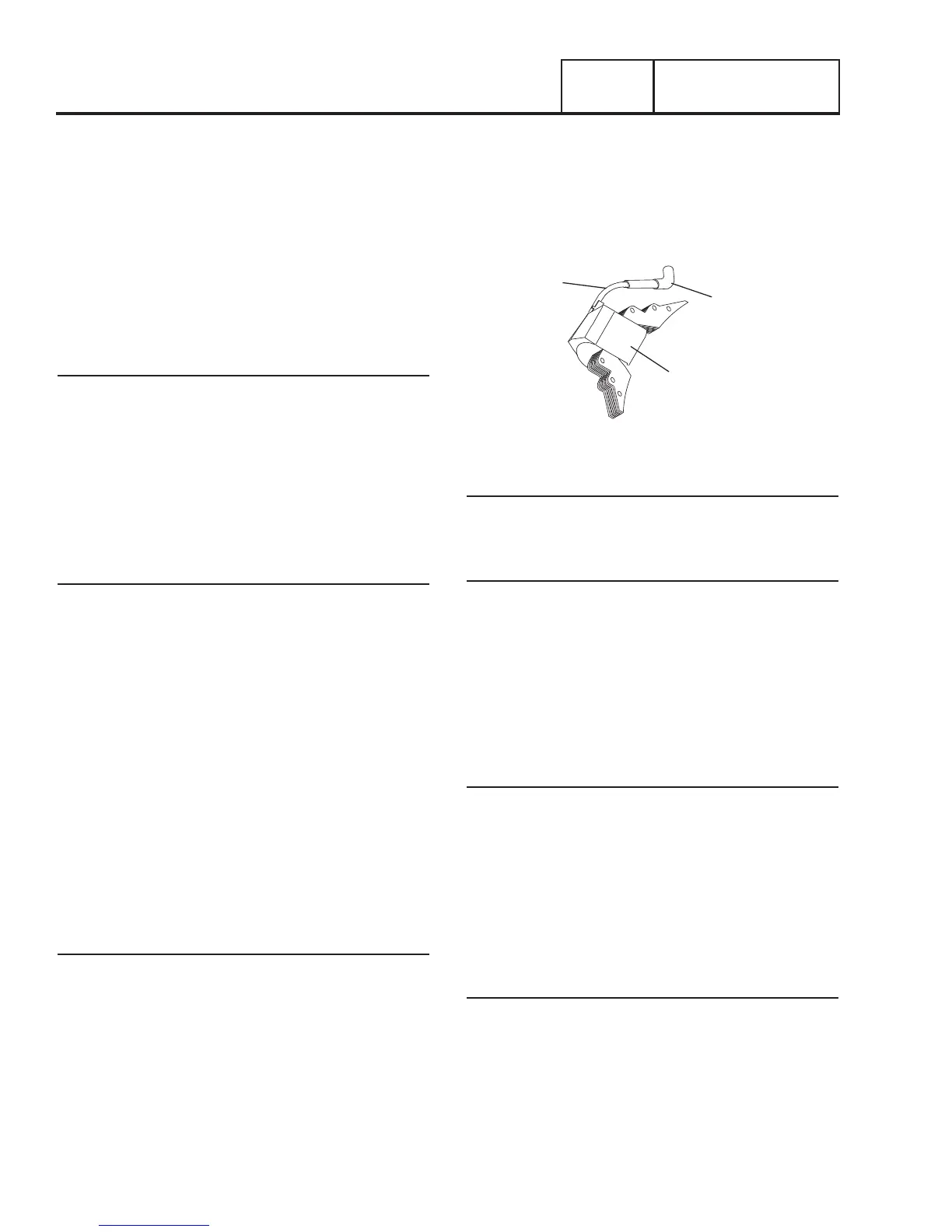
The ignition coil assembly (Figure 56) consists of (a) ignition
coil, (b) spark plug high tension lead and (c) spark plug boot.
SPARK PLUG
HIGH TENSION
LEAD
SPARK
PLUG
BOOT
IGNITION COIL
Figure 56. Ignition Coil
Procedure
1. Disconnect Wire 18 at the bullet connector and repeat
Test 67.
Results
1. If unit was able to produce spark after disconnecting Wire
18 then a short to ground is supplying Wire 18 with a
ground that is inhibiting the engine from producing spark.
2. If the Ignition Coil failed to produce spark with Wire 18
disconnected, verify integrity of Wire 18 under cover, then
replace ignition coil.
Note: Before replacing the Ignition Coil, check the flywheel
key.
Flywheel Key
In all cases, the flywheel’s taper is locked on the crankshaft
taper by the torque of the flywheel nut. A keyway is provided for
alignment only and theoretically carries no load.
If the flywheel key becomes sheared or even partially sheared,
ignition timing can change. Incorrect timing can result in hard
starting or failure to start.
TEST 68 – CHECK OIL PRESSURE SWITCH
AND WIRE 86
Discussion
If the oil pressure switch contacts have failed in their closed
position, the engine will probably crank and start. However,
shutdown will then occur within about 5 (five) seconds. If the
engine cranks and starts, then shuts down almost immediately
with a LOP fault light, the cause may be one or more of the
following:
•Low engine oil level.
•Low oil pressure.
•A defective oil pressure switch.