PART 4
ENGINE/DC CONTROL
Page 56
Section 4.3
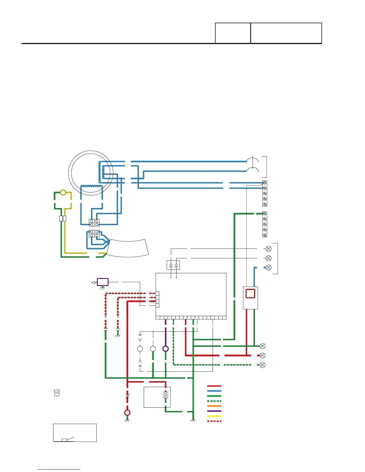
Operational Analysis
= 12 VDC ALWAYS PRESENT
= AC VOLTAGE
= GROUND
= 12 VDC DURING CRANKING ONLY
= 12 VDC DURING ENGINE RUN CONDITION
= DC FIELD EXCITATION
= 5 VDC
= PCB GROUND CONTROL
RED(+)
WHT
C1
IC
IC
INPUT
UTILITY
240 VAC
TRANSFER
+ BATTERY
GROUND
56015B23
23
0
0
BLK
0
56
RED
FS
16
13
SC
0
86
85
HTO
LOP
18
WHT
WHT
CB
15B
14
BLK
RED
BLK
12V
BATTERY
SC
0
CS
IM
SP
21
N2
N1
18
13
86
85
4
3
2
1
J1
CONTROLLER
J2
18171615141312109 1186 743 5
SM
GROUND
NEUTRAL
STATOR
WHT
BLK
WHT
BLU
WHT
GRN
BLUBLU
BLK
BA
RED
BC
RED
WIRE
+
BLK
WIRE
-
0
0
0
SUPPLIED
CUSTOMER
OUTPUT
GENERATOR
240 VAC
1
2
N1
N2
N1
1
2
CB - CIRCUIT BREAKER,
MAIN OUTPUT
GND - GROUND
HTO - HIGH TEMPERATURE SWITCH
IM - IGNITON MODULE
LOP - LOW OIL PRESSURE SWITCH
SC - STARTER CONTACTOR
SM - STARTER MOTOR
SP1 - SPARK PLUG
- SPLICE
- SPLICE INTERCONNECT
IC
BC - BATTERY CHARGER
C1 - 4 POS. CONNECTOR
LEGEND
BA - BRUSH ASSEMBLY
AWG SIZE
12
SHOWN OTHERWISE
300V UL LISTED UNLESS
NOTE: ALL WIRES 18 AWG
90
90
N1
N2
T1
RED
WHT
RED
BLK
YLW
YLW
AVR
UTILITY FAILURE AND ENGINE RUNNING
The generator is running, the controller’s engine warm up timer is timing out and the generator is producing AC voltage.
12 VDC is delivered to the actuator motor (in the EZ Transfer Operator) via wire 15B. This 12 VDC circuit is completed back to the
controller via wire 23. When the engine warm up time expires the controller will take wire 23 to ground to actuate the actuator in the
transfer switch to the generator position.
When the utility voltage returns to the controller above 75 percent of normal, the controller will energize a 15 second timer. Once the
timer has expired the controller will remove wire 23 from ground, this will actuates the actuator in the transfer switch to the normal
utility position.
Once back in the utility the controller will run the generator for 1 minute for its “cool down” cycle then shut down.
With utility available and the generator in the AUTO position the SYSTEM READY light will be solid.