PART 4
ENGINE/DC CONTROL
Page 50
Section 4.1
Description and Components
GENERAL
This section will familiarize the reader with the various
components that make up the DC control system. Major DC
control system components that will be covered include the
following:
•A Terminal Strip / Interconnection Terminal
•A Controller
•An AUTO-OFF-MANUAL Switch
•A 7.5 Amp Fuse
TERMINAL STRIP / INTERCONNECTION
TERMINAL
The terminals of this terminal strip are connected to identically
numbered terminals on a transfer switch terminal board. The
terminal board connects the transfer switch to the controller.
The terminal board provides the following connection points:
•N1 (Utility Sensing)
•N2 (Utility Sensing)
•T1 (Battery Charger)
•Wire 194 (Transfer Relay)
•Wire 23 (Transfer Relay)
E2
E1
E2
E1
T1
N2
N1
23
15B
0
(194 )
0
194
23
N1
N2
T1
Figure 32. Customer Connections
CONTROLLER
The controller controls all standby electric system operations
including (a) engine startup, (b) engine running, (c) automatic
transfer, (d) automatic retransfer, and (e) engine shutdown. In
addition, the controller performs the following functions:
•Starts and “exercises” the generator once every seven days.
•Provides automatic engine shutdown in the event of low oil
pressure, high oil temperature, overspeed, no RPM sense,
overcrank, or low battery.
An 18-pin and a 4-pin connector are used to interconnect
the controller with the various circuits of the DC systems.
Connector pin numbers, associated wires and circuit functions
are listed in the CHART on the next page.
If the Utility sensing voltage drops below a preset value,
controller action will initiate automatic generator startup and
transfer to the “Standby” source side.
The crank relay and fuel solenoid valve are energized by
controller action at the same time.
AUTO-OFF-MANUAL SWITCH
This 3-position switch permits the operator to (a) select fully
automatic operation, (b) start the generator manually, or (c)
stop the engine and prevent automatic startup.
7.5 AMP FUSE
This fuse protects the circuit board against excessive current.
If the fuse has blown, engine cranking and operation will not be
possible. Should fuse replacement become necessary, use only
an identical 7.5 amp replacement fuse.
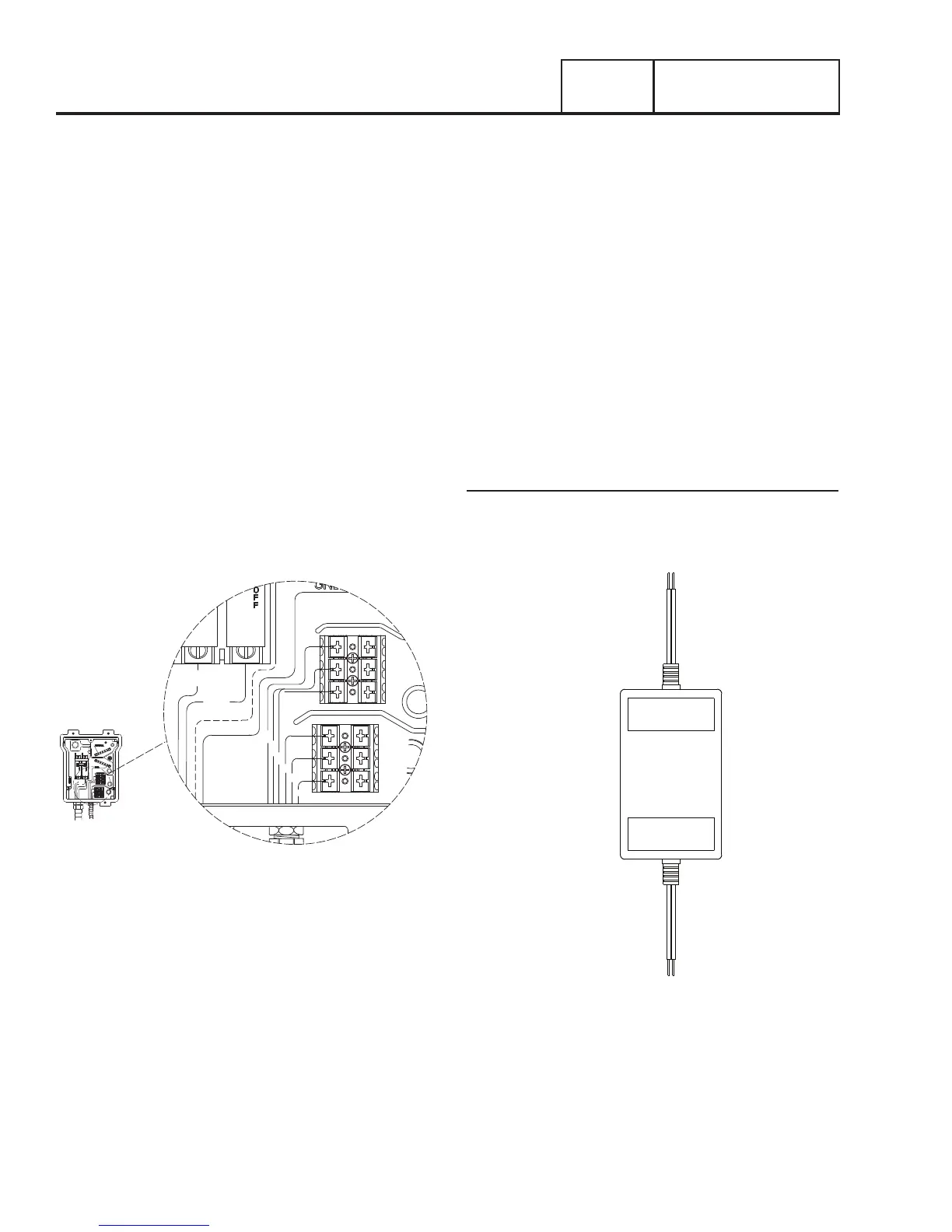
Battery Charger
The battery charger is an independent part the generator. It
has a 120 VAC input and a DC output of 13.4 VDC with a max
amperage of 2.5 amps.
AC INPUT
DC OUTPUT
Figure 33. Battery Charger