AC GENERATORS
PART 2
Page 33
Section 2.4
Diagnostic Tests
TEST 9 – TEST THE STATOR
Discussion
This test will use a Volt-Ohm-Milliammeter (VOM) to test the
stator windings for the following faults:
•An OPEN circuit condition
•A “short-to-ground” condition
•A short circuit between windings
Table 7 has been provided to record the results of the following
procedure. These results may be required when requesting
factory support.
Additional copies of Table 7 can be found in Appendix A
“Supplemental Worksheets” at the back of this manual.
Note: It is the recommendation of the factory to perform
this test procedure using piercing probes on the wire
side of the connector. Testing inside the connector itself
can cause damage to the unit resulting in poor or loose
connections.
Stator Resistances
•Power Windings
White/Blue = .173 Ohms
White/Black = .173 Ohms
Blue/Black = .346 Ohms
•Sensing Winding
Green/White = .064 Ohms
•DPE Winding
Blue/Blue = 1.158 Ohms
Procedure: Resistance Test
1. Disconnect the Blue and Black Wires from the main line
circuit breaker (MLCB).
2. Disconnect the C1 connector from the voltage regulator.
3. Make sure all of the disconnected leads are isolated from
each other and are not touching the frame during the test.
4. Set the VOM to measure resistance.
5. Measure and record the resistance values for each set
of windings between the A and B test points as shown in
Table 4. Record the results in Table 7.
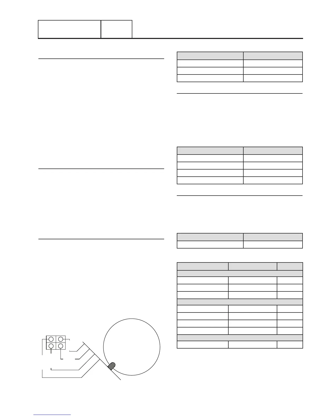
STATOR
C1
BLUE
WHITE
BLUE
GREEN
1
2
3
4
Figure 22. Stator Lead Connections
Table 4. Test Points – Resistance Tests
Test Point A Test Point B
Stator Lead Blue Wire Stator Lead Black Wire
Stator Lead Blue Wire C1 Pin 3 (White Wire)
Stator Lead Blue Wire C1 Pin 4 (Green Wire)
Test Windings for a Short to Ground
6. Make sure all stator leads are isolated from each other
and are not touching the frame.
7. Measure and record the resistance values for each set
of windings between the A and B test points as shown in
Table 5. Record the results in Table 7.
Table 5. Test Points – Shorts to Ground
Test Point A Test Point B
Stator Lead Blue Wire Ground
Stator Lead Black Wire Ground
C1 Pin 1 Wire 44 (Blue Wire) Ground
C1 Pin 4 (Green Wire) Ground
Test For A Short Circuit Between Windings
8. Measure and record the resistance values for each set
of windings between the A and B test points as shown in
Table 6. Record the results in Table 7.
Table 6. Test Points – Shorted Condition
Test Point A Test Point B
C1 Pin 1 (Blue Wire) Stator Lead Blue Wire
Table 7. Stator Test Results
Test Point A Test Point B Results
Resistance Tests
Stator Lead Blue Wire Stator Lead Black Wire
Stator Lead Blue Wire C1 Pin 3 (White Wire)
Stator Lead Blue Wire C1 Pin 4 (Green Wire)
Shorts to Ground
Stator Lead Blue Wire Ground
Stator Lead Black Wire Ground
C1 Pin 1 Wire 44 (Blue Wire) Ground
C1 Pin 4 (Green Wire) Ground
Shorted Condition
C1 Pin 1 (Blue Wire) Stator Lead Blue Wire
Note: These results may be needed when requesting
factory support.
Note: Stator winding resistance values are very low and
some VOM’s will not read such a low resistance, and
will simply indicate CONTINUITY. The manufacturer
recommends a high quality digital type meter capable of
reading a very low resistance.