ENGINE/DC CONTROL
PART 4
Page 73
Section 4.5
Diagnostic Tests
Procedure
1. Check engine crankcase oil level.
a. Check engine oil level.
b. If necessary, add the recommended oil to the dipstick
FULL mark. DO NOT OVERFILL ABOVE THE FULL
MARK.
2. With oil level correct, try starting the engine.
a. If engine still cranks and starts, but then shuts down,
go to Step 4.
b. If engine cranks and starts normally, discontinue tests.
3. Do the following:
a. Disconnect Wire 86 and Wire 0 from the oil pressure
switch terminals. Remove the switch and install an oil
pressure gauge in its place.
b. Start the engine while observing the oil pressure
reading on gauge.
c. Note the oil pressure.
(1) Normal oil pressure is approximately 35-40 psi with
engine running. If normal oil pressure is indicated, go
to Step 4 of this test.
(2) If oil pressure is below about 4.5 psi, shut engine
down immediately. A problem exists in the engine
lubrication system.
Note: The oil pressure switch is rated at 10 psi for single
cylinder engines.
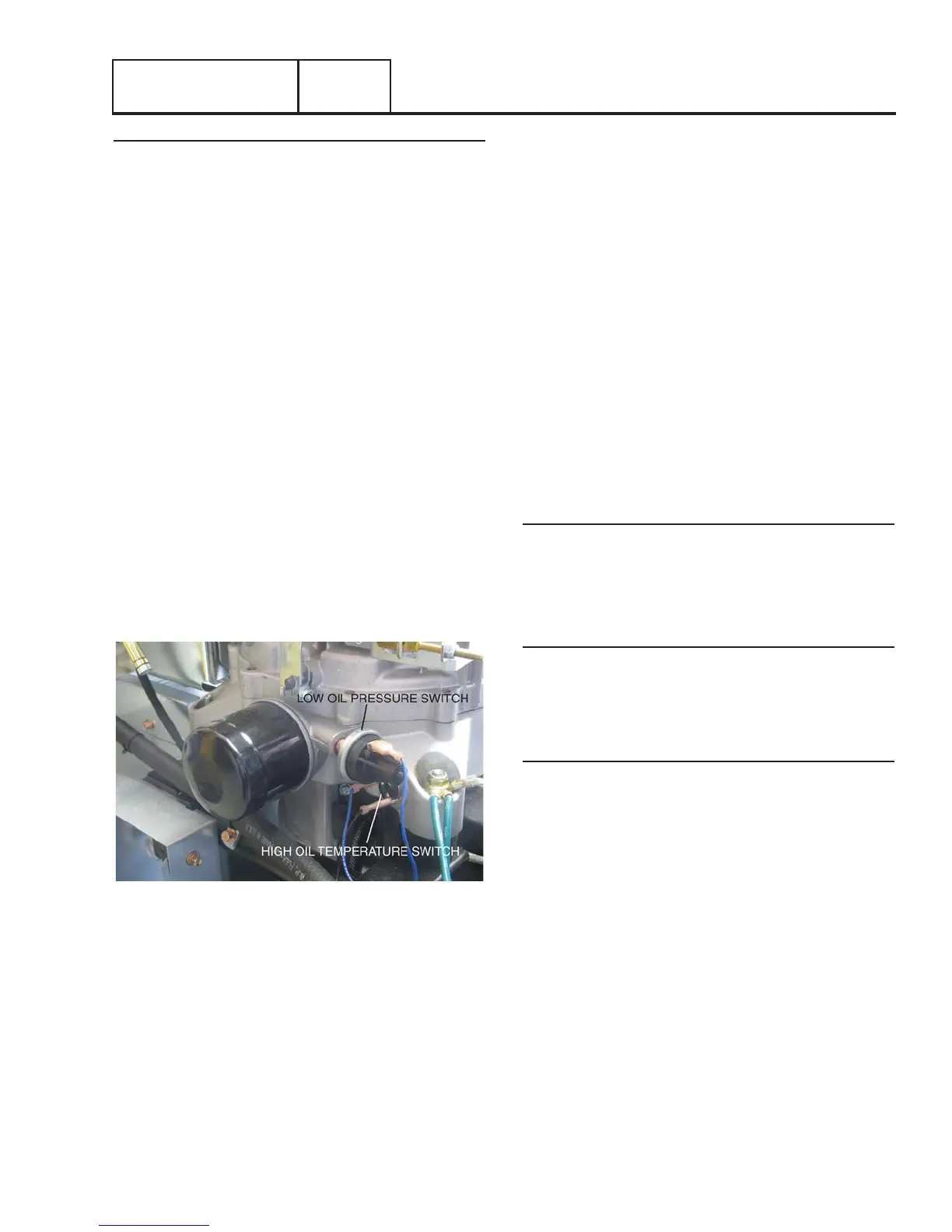
Figure 57. Oil Pressure Switch
4. Remove the oil pressure gauge and reinstall the oil
pressure switch. Do NOT connect Wire 86 or Wire 0 to
the switch terminals.
a. Set a VOM to measure resistance.
b. Connect the VOM test leads across the switch
terminals. With engine shut down, the meter should
read CONTINUITY. If INFINITY is measured with the
engine shutdown, replace the LOP switch.
c. Crank and start the engine. The meter should read
INFINITY.
5. Set a VOM to measure resistance.
a. Disconnect the J1 Connector from the controller.
b. Connect one test lead to Wire 86 (disconnected from
LOP). Connect the other test lead to Pin Location 4
(Wire 86) of the J1 Connector at the controller.
CONTINUITY should be measured. If CONTINUITY is not
measured, repair or replace Wire 86 between the LOP
switch and the J1 Connector.
c. Connect one test lead to Wire 0 ( disconnected from
LOP). Connect the other test lead to a clean frame ground.
CONTINUITY should be measured. If CONTINUITY is NOT
measured repair or replace Wire 0 between the LOP and the
ground terminal connection on the engine mount.
6. If the LOP switch tests good in Step 5 and oil pressure
is good in Step 4 but the unit still shuts down with a LOP
fault, check Wire 86 for a short to ground. Set a VOM to
measure resistance. Disconnect the J1 Connector from the
controller. Remove Wire 86 from the LOP switch. Connect
one test lead to Wire 86. Connect the other test lead to
a clean frame ground. INFINITY should be measured.
If CONTINUITY is measured, repair or replace Wire 86
between the LOP switch and the J1 Connector.
Results
1. Replace switch if it fails the test.
TEST 69 – CHECK HIGH OIL TEMPERATURE
SWITCH
Discussion
If the temperature switch contacts have failed in a closed position,
the engine will fault out on “OVERTEMP.” If the unit is in an
overheated condition, the switch contacts will close at 293° F. This
will normally occur from inadequate airflow through the generator.
Procedure
1. Verify that the engine has cooled down (engine block is
cool to the touch). This will allow the contacts in the High
Oil Temperature Switch to close.
2. Check the installation and area surrounding the generator.
There should be at least three feet of clear area around
the entire unit. Make sure that there are no obstructions
preventing incoming and outgoing air.
3. Disconnect Wire 85 and Wire 0 from the High Oil
Temperature Switch.
4. Set a VOM to measure resistance. Connect the test
leads across the switch terminals. The meter should read
INFINITY.
5. If the switch tested good in Step 4, and a true
overtemperature condition has not occurred, check Wire
85 for a short to ground. Remove J1 Connector from the
controller. Set the VOM to measure resistance. Connect
one test lead to Wire 85 (disconnected from High Oil
Temperature Switch). Connect the other test lead to a clean
frame ground. INFINITY should be measured.