ENGINE/DC CONTROL
PART 4
Page 77
Section 4.5
Diagnostic Tests
TEST 77 – CHECK BATTERY CHARGER
OUTPUT VOLTAGE
Discussion
The battery charger is supplied with 120 VAC. The output of
the battery charger is 13.4 VDC (2.5A).
Procedure
Refer to Figure 62.
1. Set VOM to measure DC voltage.
2. Remove and isolate battery charger black and red leads
from generator terminal strip points E and F.
3. Measure across points E and F. Battery supply voltage (12
VDC) should be measured.
a. If battery voltage is not measured, wait 5 minutes
and repeat Step 3. If battery supply voltage is still not
available, refer to Flow Chart.
b. If battery voltage is measured, proceed to Step 4.
4. Reconnect battery charger black and red lead wires
previously removed in Step 2.
5. Measure across points E and F. 13.4 VDC should be
measured.
a. If 13.4 VDC is not measured, replace the battery
charger.
b. If 13.4 VDC is measured, the charger is working.
NOTE: Battery charger voltage will be higher than battery
supply voltage.
TEST 78 – CHECK WIRE 0/15B
Discussion
In order for the battery charger to function, battery supply voltage
must be available to the battery charger.
Procedure
Refer to Figure 62.
1. Set VOM to measure DC voltage.
2. Remove and isolate battery charger black and red leads
from generator terminal strip points E and F.
3. Measure across points G and H on the terminal strip. 12
VDC should be measured.
a. If 12 VDC is measured, the charger should be
functioning.
b. If 12 VDC is not measured, proceed to Step 4.
4. Remove Wire 0 and Wire 15B from generator terminal
strip locations E and F.
5. Wait five (5) minutes after removing wires.
6. Measure across points E and F on the terminal strip.
12 VDC should be measured.
a. If 12 VDC is measured, proceed to Step 8.
b. If 12 VDC is not measured, proceed to Step 7.
7. Measure across point H and ground lug. 12 VDC should
be measured.
a. If 12 VDC is measured, repair or replace Wire 0
between the generator terminal strip and the ground
lug.
b. If 12 VDC is not measured, proceed to Step 8.
8. Set VOM to measure resistance.
9. Connect the meter test leads across the disconnected
Wire 0 and Wire 15B. Approximately 200 Ohms should
be measured.
a. If 200 Ohms is measured, proceed to Step 11.
b. If zero resistance or CONTINUITY is measured, connect
the meter test leads across BAT- and XFER on the load
center motor.
c. If zero resistance is measured, a short exists. Replace
the load center motor.
d. If 200 Ohms to INFINITY is measured, repair or replace
Wire 15B between the generator and the load center.
10. Disconnect the J2 connector from the controller.
11. Measure across point F and pin location J2-8 of the
connector just removed. CONTINUITY should be
measured.
a. If CONTINUITY is not measured, repair or replace Wire
15B between the J2 connector and the terminal strip.
b. If CONTINUITY is measured and the pin connection
looks good, the internal fuse on the controller has failed.
Replace the controller.
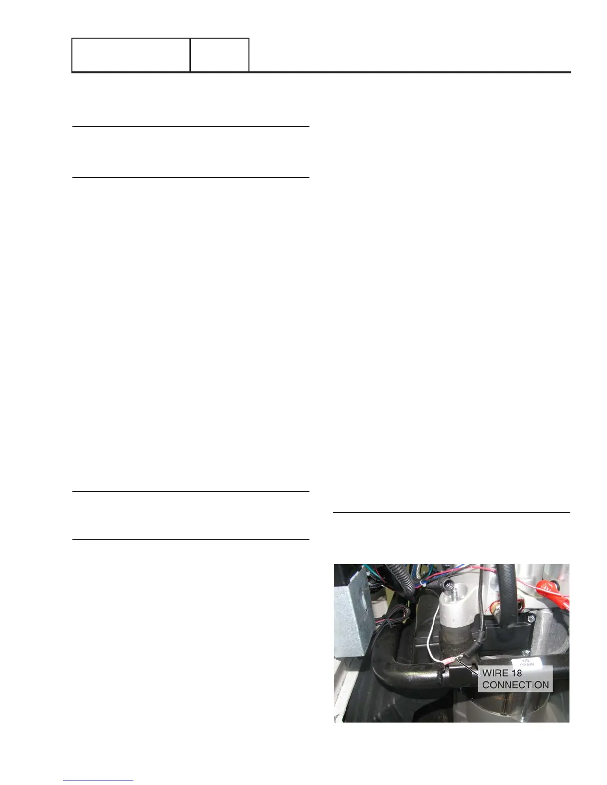
TEST 79 – CHECK SHUTDOWN WIRE
Discussion
Circuit board action during shutdown will ground Wire 18.
Wire 18 is connected to the Ignition Magneto(s). The grounded
magneto will not be able to produce spark.
Figure 61. Wire 18 Connection