AC GENERATORS
PART 2
Page 25
OTHER AC GENERATOR COMPONENTS
Located within the generator control panel enclosure are the
voltage regulator and the main line circuit breaker.
Voltage Regulator
Unregulated AC output from the stator excitation winding is
delivered to the regulator’s DPE circuit through the two Blue
wires and C1-1 and C1-2. The voltage regulator rectifies
that voltage and, based on stator AC power winding sensing,
regulates it. The rectified and regulated field excitation current is
then delivered to the rotor windings from the positive (+) Red
Wire and negative (-) Black Wire (originates as White Wire from
regulator and changes to Black at the C1 connector). Stator AC
power winding “sensing” is delivered to the regulator through
the Green and White Wires.
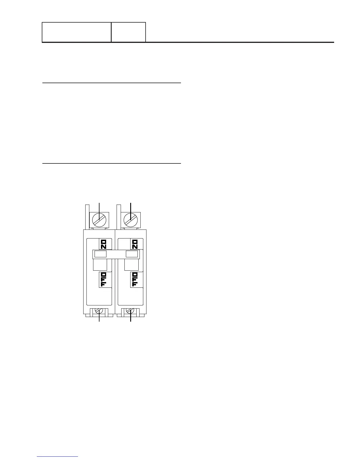
Main Line Circuit Breaker
The main line circuit breaker protects the generator against
electrical overload. Refer to “Specifications” section for the
specific amperage ratings.
LOAD SIDE
E1 E2
LINE
BLUE BLACK
Figure 17. Main Line Circuit Breaker
Section 2.1
Description and Components