PART 4
ENGINE/DC CONTROL
Page 74
Section 4.5
Diagnostic Tests
Testing High Oil Temperature Switch
6. Remove the High Oil Temperature Switch.
7. Immerse the sensing tip of the switch in oil as shown in
Figure 58, along with a suitable thermometer.
8. Set a VOM to measure resistance. Then, connect the VOM
test leads across the switch terminal and the switch body.
The meter should read INFINITY.
9. Heat the oil in the container. When the thermometer reads
approximately 283°-305° F. (139°-151° C.), the VOM
should indicate CONTINUITY.
Results
1. If the switch fails Step 4, or Steps 8-9, replace the switch.
2. If INFINITY was NOT measured in Step 5, repair or
replace Wire 85 between the controller and the High Oil
Temperature Switch.
Figure 58. Testing the Oil Temperature Switch
TEST 70 – CHECK AND ADJUST VALVES
Discussion
Improperly adjusted valves can cause various engine related
problems including, but not limited to, hard starting, rough
running and lack of power.
Procedure
1. The engine should be cool before checking. If valve
clearance is 0.006"-0.008" (0.15-0.20mm), adjustment is
not needed.
2. Remove spark plug wire and position wire away from
plug.
3. Remove spark plug.
4. Make sure the piston is at Top Dead Center (TDC) of
its compression stroke (both valves closed). To get the
piston at TDC, remove the intake screen at the top of the
engine to gain access to the flywheel nut. Use a large
socket and socket wrench to rotate the nut and hence the
engine in a clockwise direction. While watching the piston
through the spark plug hole. The piston should move up
and down. The piston is at TDC when it is at its highest
point of travel.
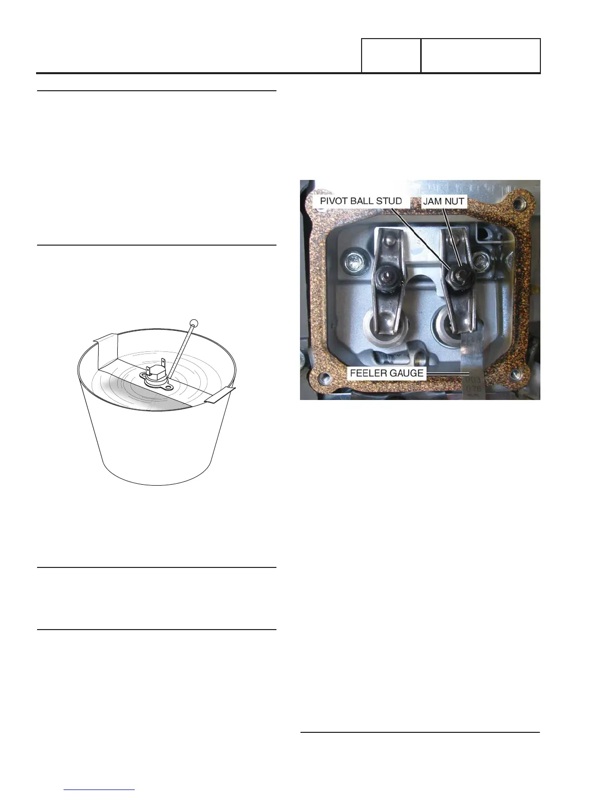
Figure 59. Valve Train
5. Remove the four screws attaching the valve cover.
6. Loosen the rocker jam nut. Use a wrench to turn the pivot
ball stud while checking clearance between the rocker
arm and the valve stem with a feeler gauge. Correct
clearance is:
Intake — 0.005-0.007 inch (0.13-0.17 mm)
Exhaust — 0.007-0.009 inch (0.18-0.22 mm)
NOTE: Hold the rocker arm jam nut in place as the pivot
ball stud is turned.
7. When valve clearance is correct, tighten the rocker arm
jam nut. Tighten the jam nut to 70 to 106 in-lbs. torque.
After tightening the jam nut, recheck valve clearance to
make sure it did not change.
8. Install new valve cover gasket.
9. Re-attach the valve cover.
NOTE: Start all four screws before tightening or it will not
be possible to get all the screws in place. Make sure the
valve cover gasket is in place.
10. Install spark plug.
11. Re-attach the spark plug wire to the spark plug.
Results
Adjust valve clearance as necessary, then retest.