PART 3
TRANSFER SWITCH
Page 38
Section 3.1
Description and Components
GENERAL
The 50 amp transfer switch is designed to operate in conjunction
with all product which utilizes the Wire 194/15B and Wire 23
control systems. Utility voltage and the control panel on the
generator controls sequence delays. The AUTO-OFF-MANUAL
switch must be in the AUTO position for automatic operation of
the transfer switch.
ENCLOSURE
The standard switch enclosure is a National Electrical
Manufacturer’s Association (NEMA) UL Type 1.
EZ TRANSFER OPERATOR
The EZ Transfer Operator is a rotary device that actuates the
arms that push two standard 2-pole breakers, transferring
the load from Utility to Generator. The operator returns to
a “Neutral” position so the arms move freely and allow the
manual operation of the breakers.
The operator is suited for single-phase applications only, when
the single-phase NEUTRAL line is to be connected to a Neutral
Lug and is not to be switched.
Internal Components
Three components make up the operator: the servomotor, Limit
Switch 1 (LS1), and Limit Switch 2 (LS2). The servomotor is
responsible for changing the position of the breakers inside
the switch. Both limit switches are responsible for interrupting
current flow to the servomotor once the transfer cycle is
complete.
Figure 26. EZ Transfer Operator
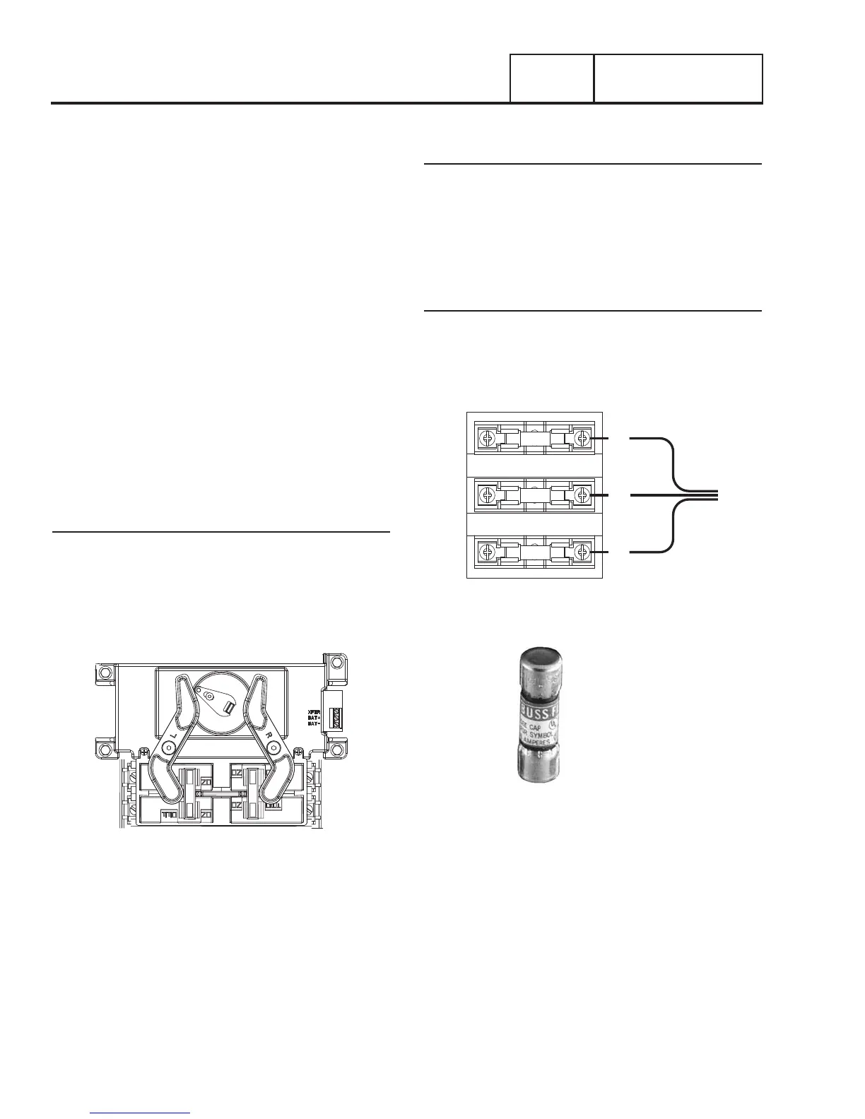
FUSE HOLDER
Utility N1 and N2
N1 and N2 provide the Utility voltage-sensing signal to the
controller. The controller utilizes the sensing circuit as follows:
•If Utility source voltage should drop below 65% of nominal
for ten seconds, the controller’s logic will initiate automatic
cranking and startup. The controller will transfer the switch
to the Standby position after a five second engine warm-up
timer.
Load T1
Wire T1, connected to the Load side of the switch, provides 120
VAC for the battery charging. The charger maintains battery
voltage anytime the load terminals have voltage available.
T1
N2
N1
Figure 27. Fuse Holder
5 AMP 600V RATING
FAST ACTING
BUSSMANN PART# BBS-5
Figure 28. Fuse