104
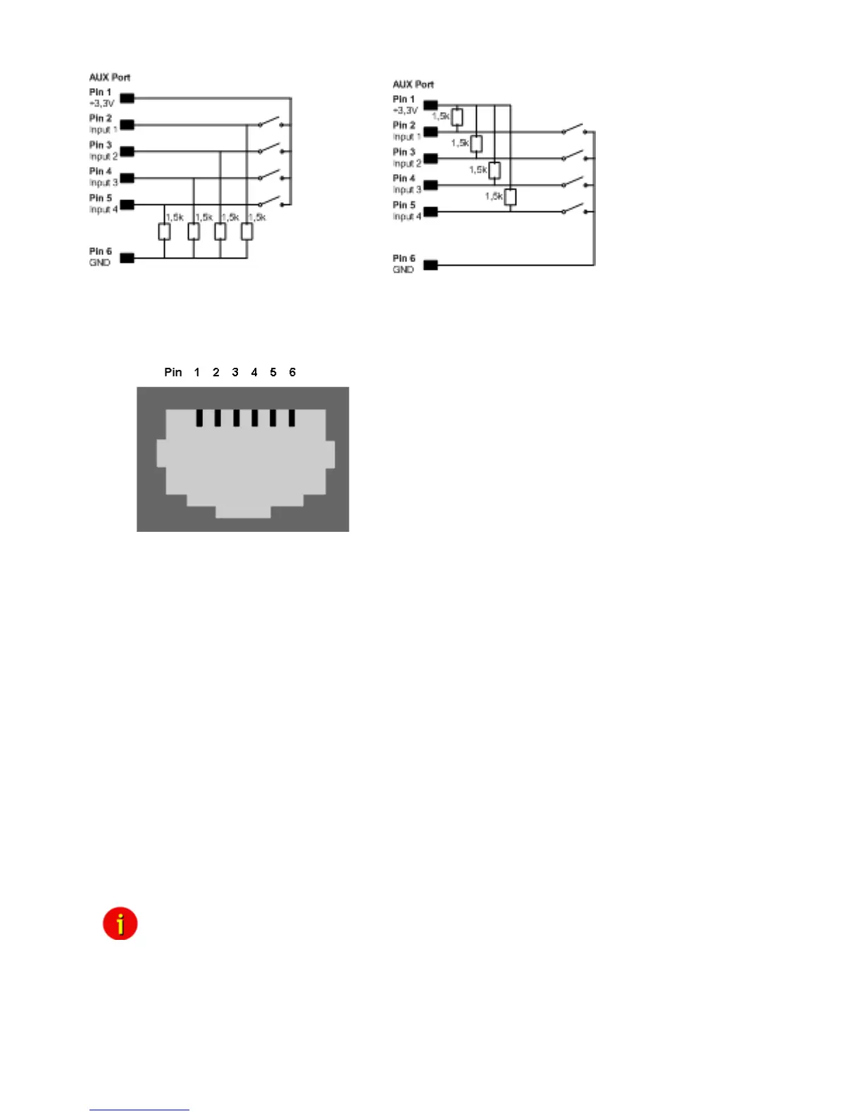
Figure 135: Examples: AUX Input on hardware model CS131 only, left side “pull-down”, right
side “pull-up” configuration
Figure 136: AUX Port Assignment
AUX port assignment for CS121 HW131 L from serial number 0121-10417 and CS121 HW131
SC from serial number 0123-09428:
PIN 1: 3,3V
PIN 2: AUX port 0: disposable
PIN 3: AUX port 1: disposable
PIN 4: AUX port 2: RX from COM3 (input)
PIN 5: AUX port 3: TX from COM3 (output)
PIN 6: GND
D. MODBUS Interface
D.1. General information
For remote control and monitoring of devices the MODBUS interface in each CS121 M can
read out measurement values, events, status and other information in a master-slave protocol.
Note: Please note that not all UPS models support all or specific measurement
values (e.g. battery low).
Communication Parameters:
ASCII Mode works at CS131 & CS121 platforms with communcation
parameters 7/E/2, or 7/E/1 or with 7/N/2 from baudrate 1200 to 38400. We