EasyManua.ls Logo

Generex CS121BL - UPSMAN Status Bytes - Standard Device Status Bits; Bus Termination

Default Icon
141 pages
Print Icon
To Next Page IconTo Next Page
To Previous Page IconTo Previous Page
Loading...
119
D.6. UPSMAN Status Bytes - Standard Device Status Bits
UPS Status
Hex-Value
Dec-Value
Description
UPS_SB_BYPASS_MODE
0x0001
1
power piped thru
UPS_SB_SHUTDOWN
0x0002
2
shutdown ups
UPS_SB_OUTPUT_ACT
0x0004
4
inverter on = UPS OK
UPS_SB_BACKUP_MODE
0x0008
8
battery power
UPS_SB_BATTERY_LOW
0x0010
16
low battery err
UPS_SB_OVER_TEMP
0x0020
32
over temp err
UPS_SB_TEST_ACT
0x0040
64
test in progress
UPS_SB_INPUT_HIGH
0x0080
128
over power err
UPS_SB_OUTPUT_HIGH
0x0100
256
over load err
UPS_SB_INVERTER_FAILURE
0x0200
512
Inverter error
UPS_SB_BATTERY_BAD
0x0400
1024
Battery error
UPS_SB_ECO_MODE
0x0800
2048
eco - bypass
UPS_SB_INVERTER_WARN
0x1000
4096
eco - bypass
UPS_SB_UPS_FAILED
0x2000
8192
prser flag
UPS_SB_COMM_LOST
0x4000
16384
for snmp
UPS_SB_DVG_ALARM
0x8000
32768
SiteManager/SiteMonitor
Example (decimal):
STATUS= „5” means UPS_SB_OUTPUT_ACT (4) + UPS_SB_BYPASS_MODE (1) are active
! = UPS on Bypass!
STATUS= „12” means UPS_SB_OUTPUT_ACT (4) + UPS_SB_BACKUP_MODE (8) are
active ! = UPS Powerfail!
STATUS= „22” means UPS_SB_OUTPUT_ACT (4) + UPS_SB_BACKUP_MODE (8) +
UPS_SB_BATTERY_LOW (10) are active ! = UPS Powerfail and Battery low!
STATUS= „4” means UPS_SB_OUTPUT_ACT (4) + no other alarms = UPS OK
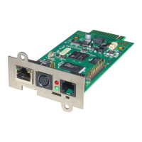
D.7. Bus termination
It is necessary to set the last bus device on the RS-485 Bus jumper for the bus termination.
(120 Ohm) The jumper is already set in newly delivered adapters. Please remove the 4 screws
at the underside of the adapter in order to open the box. You will find the jumper J1 near the
network connector, near the PCB shows a “+” symbol. (see fig.) Default is OFF = CS121 is
NOT last device. To terminate the RS485 bus at your CS121, please close the Jumper.

Table of Contents

Related product manuals