24
3. Configuration of the CS121
Note: After you have finished the basic network configuration you should have
set DIP-switch 1 in position ON and rebooted the adapter. At the SC slot
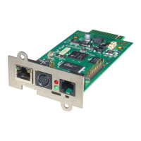
cards you have to remove the card from its slot and change the DIP
Switch 1 to position ON. After this, re-insert the card. Info: There is no
risk to remove/insert the slot card, there will be no effect on the UPS
output.
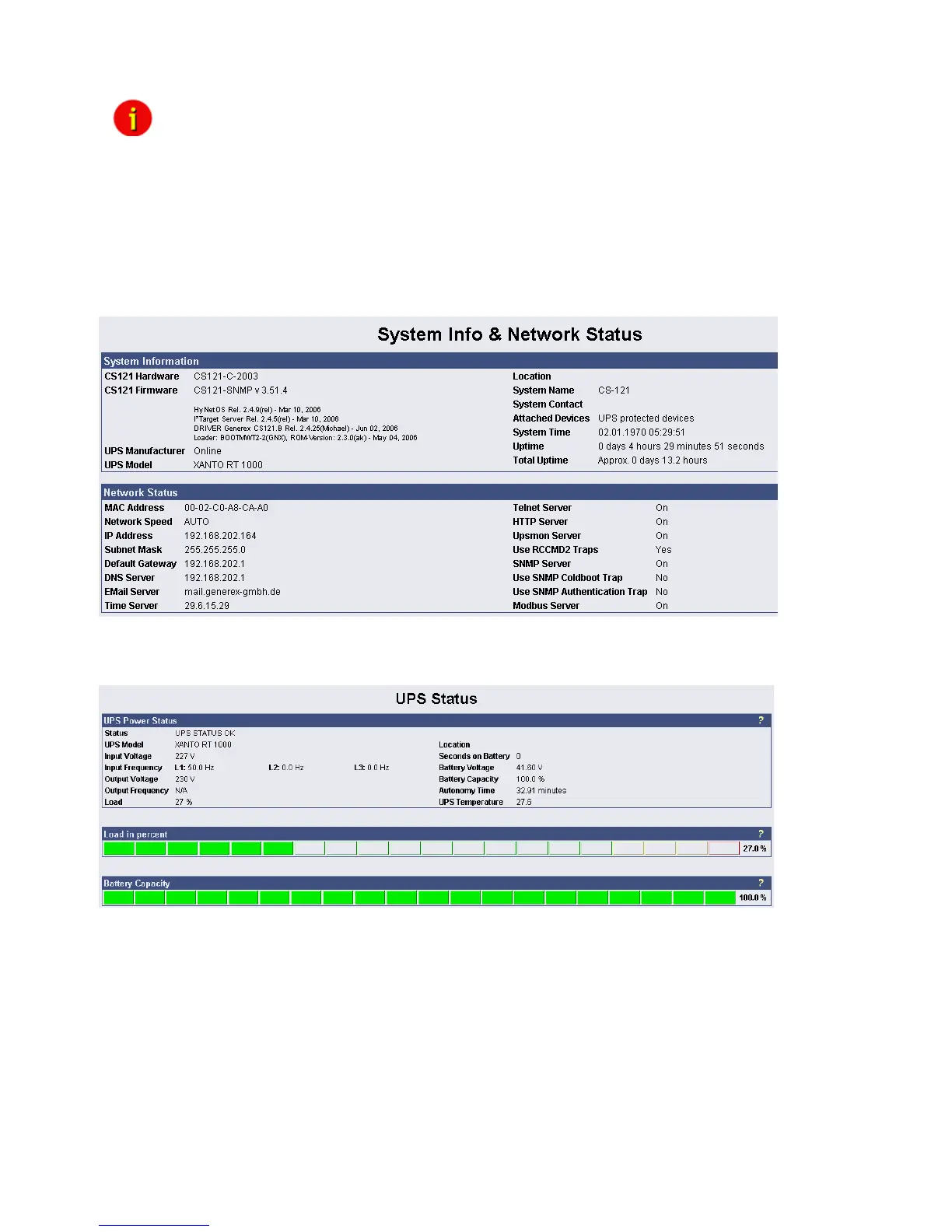
3.1 CS121 Status-Monitors
The Menu “System & Network Status” shows basic information about general configuration
settings:
Figure 13: HTTP - System & Network Status
The Menu “UPS Status” gives information about the actual UPS-data, above all the state of
charge and battery load:
Figure 14: HTTP - UPS Status
The Menu “UPS functions” allows you to perform USV test- and control-scenarios like battery
tests, etc. The UPS functions depend on the UPS type and its functions. Some UPS only allow
a remote on/off, others have more functions.