11
1.5 CS121 overview
For CS121L, C and Slot card types
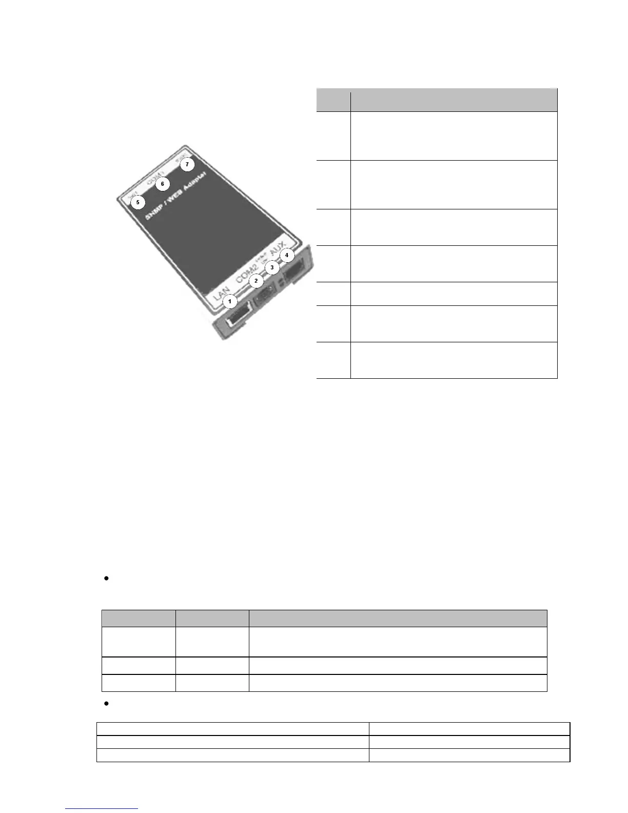
Figure 1: Connectors of the CS121
CS121 family:
CS121L = external device with external power supply 9V (US: 12V)
CS121SC = slot device for Chinese UPS with slot (also as BUDGET, CS121BSC).
CS121F = slot device for FUJI UPS Japan
CS121R = slot device for RIELLO/AROS UPS Italy
CS121MOD = external device with MODBUS RS485 port
CS121CS MOD = slot device with MODBUS RS485 port
CS121BL = external device BUDGET-Model (does not have COM2- and AUX-port)
CS121BSC = slot device BUDGET-Model (does not have COM2- and AUX-port)
The CS121 FirmWare Version 4.30.x provides devices, which are running with 88MHz only.
Those kind of devices have to be selected, if the power supply is not sufficient. With the
selection of a 88MHz device, the power consumption of the CS121 will be halved. Therefore
an operation into weak supplied UPS slots is possible.
(1) LED-Status of Network connectivity: The LEDs which are integrated into the RJ45
connector (see No. 1 in the figure above) will signal with green a connection to the network
and with yellow network communication.
Network connection RJ45 10/100 Base T
Connector (with Status LED, green=link,
yellow=activity)