14.5 Connecting the Camera
Connect your Vandal Proof IP Dome to power, network and other cables
needed.
14.5.1 Wire Definition
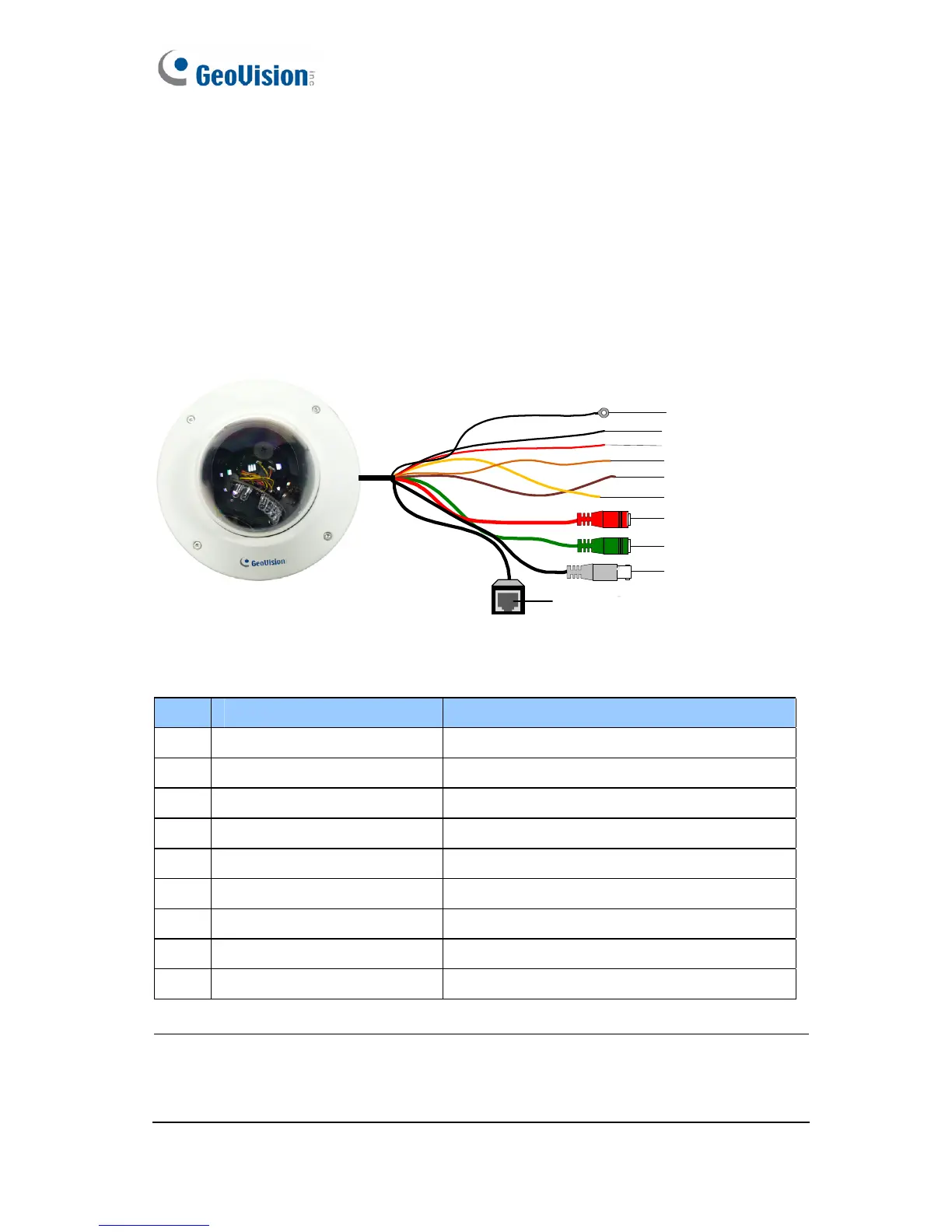
The cables of Vandal Proof IP Dome are illustrated and defined below.
Ethernet (PoE)
TV out
Audio out (green)
Audio in (red)
Digital in (oragne)
Ground (yellow)
Digital out (brown)
Shielding ground
DC 12V+ / AC 24V+
DC 12V- / AC 24V-
Figure 14-14
No. Wire Color Definition
1 Black (thick) Shielding Ground
2 Black (thin) DC 12V- / AC 24V-
3 Red DC 12V+ / AC 24V+
4 Orange Digital In
5 Brown Digital out
6 Yellow Ground
7 Red RCA Audio in
8 Green RCA Audio out
9 Black BNC TV out
Note: To use the TV out function, connect the black BNC connector to a
monitor and select your signal format (NTSC or PAL) at the
TV Out field
on the Web interface. For details, see 21.1.1 Video Settings.
206
 Loading...