Advanced Cube Camera
217
21
No. Name Description
8 Stand screw Connects to the Supporting Rack.
9 Power port Connects to the power adapter.
10 Ready LED
Reflects system status of the camera. See the
below table.
11 LAN LED
Reflects LAN status of the camera. See the below
table.
12
Memory
Card Slot
Receives a micro SD card (SD/SDHC, version 2.0
only, Class 10) to store recording data.
IMPORTANT: The White Illumination LED can reach high temperatures.
Be sure not to touch the LED with bare hand.
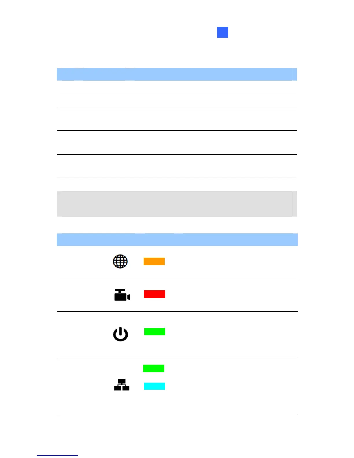
LED Status Description
Live View
Turns on orange light when you
see the live view.
Monitoring
Turns on red light when you
start monitoring.
Ready
Turns on green light when the
system is ready.
Flashes green light when you
load default value.
LAN
Turns on green light when you
connect the LAN Network.
Turns on blue light when you
connect the Wi-Fi Network (for
GV-CAW120 / 220 only).
 Loading...