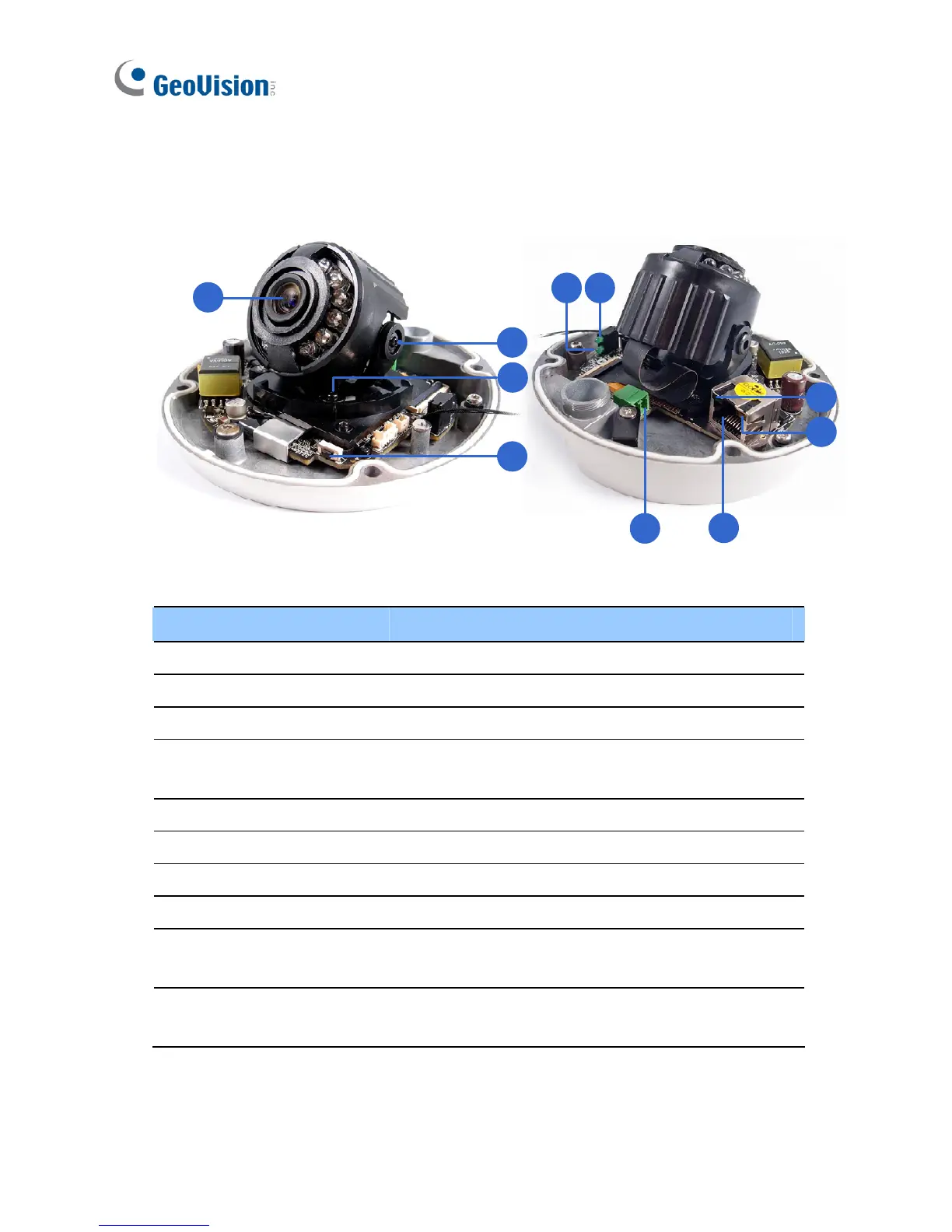
EasyManuals Logo

GeoVision GV-IPCamera Series User Manual

GeoVision GV-IPCamera Series
306 pages
To Next Page IconTo Next Page
To Previous Page IconTo Previous Page
Page #90 background imageLoading...
Page #90 background image
56
7.2 Overview
5
d
a b
6
c
1
3
2
4
No. Name Description
1 Lens Receives image inputs.
2 Pan Screw Loosens the screw to adjust pan angle.
3 Tilt Screw Loosens the screw to adjust tilt angle.
4 Default Button
Resets the camera to default settings. See 27.
Restoring to Default Settings.
5 DC 12V Port Connects to power.
6 LAN / PoE Connects to a 10/100 Ethernet or PoE.
a Status Turns on (green) when the system is ready.
b Power Turns on (green) when power is on.
c Link
Turns on (green) when the network is
connected.
d ACT
Turns on (orange) when data are being
transmitted.

Table of Contents

Other manuals for GeoVision GV-IPCamera Series

Questions and Answers:

Question and Answer IconNeed help?

Do you have a question about the GeoVision GV-IPCamera Series and is the answer not in the manual?

GeoVision GV-IPCamera Series Specifications

General IconGeneral
BrandGeoVision
ModelGV-IPCamera Series
CategorySecurity Camera
LanguageEnglish

Related product manuals