EasyManuals Logo

GeoVision GV-IPCamera Series User Manual

GeoVision GV-IPCamera Series
306 pages
To Next Page IconTo Next Page
To Previous Page IconTo Previous Page
Page #109 background imageLoading...
Page #109 background image
Bullet Camera (Part I)
75
8
8.4 Connecting the Camera
Connect your Bullet Camera to power, network and the cables needed.
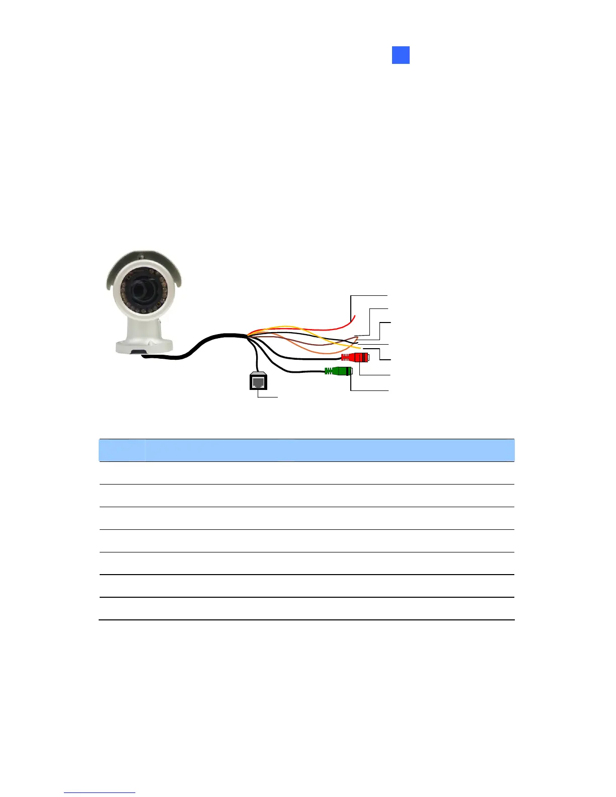
8.4.1 Wire Definition
The cable of the Bullet Camera is illustrated and defined below:
Ethernet (PoE)
Digital In (Red)
DC 12V+ / AC 24V + (Brown)
Digital Out (Orange)
DC 12V- / AC 24V - (Black)
GND (Yellow)
Audio In (Red)
Audio Out (Green)
No. Wire Color Definition
1 Red Digital In
2 Brown DC 12V+ / AC 24V+
3 Orange Digital Out
4 Black DC 12V- / AC 24V-
5 Yellow Ground
6 Red RCA Audio in
7 Green RCA Audio out

Table of Contents

Other manuals for GeoVision GV-IPCamera Series

Questions and Answers:

Question and Answer IconNeed help?

Do you have a question about the GeoVision GV-IPCamera Series and is the answer not in the manual?

GeoVision GV-IPCamera Series Specifications

General IconGeneral
BrandGeoVision
ModelGV-IPCamera Series
CategorySecurity Camera
LanguageEnglish

Related product manuals